Valve timing controller

a timing controller and valve technology, applied in the direction of valve arrangements, yielding couplings, couplings, etc., can solve the problems of large stroke range, long spool valve stoke, and large size of valve timing controllers, so as to achieve small stroke range and short stroke of valve members.

Active Publication Date: 2010-07-15
DENSO CORP
View PDF2 Cites 20 Cited by
  • Summary
  • Abstract
  • Description
  • Claims
  • Application Information

AI Technical Summary

Benefits of technology

[0016]When the valve member moves to be positioned in the lock range in which the operation port and the lock port are respectively communicate with the supply port and the discharge port, the hydraulic fluid is introduced into the hydraulic chamber and the hydraulic fluid is discharged from the lock chamber to lock the vane rotor relative to the housing. When the valve member moves to be positioned in the stroke range in which both of the operation port and the lock port communicate with the supply port, the hydraulic fluid is introduced from the fluid supply source into the hydraulic chamber and the lock chamber, so that the vane rotor can be rotated to vary the rotational phase thereof. The stroke range of the valve member deviates from the lock range in the second direction. The lock range includes a stroke end of the valve member in the first direction which corresponds to a direction of a biasing force of the biasing means. In other words, since the lock range deviates from the stroke range in the biasing direction, when the hydraulic fluid supply and the driving force are stopped, the valve member is displaced by only biasing force to lock the vane rotor.
[0017]Furthermore, when the valve member moves to be positioned at a limit position of the stroke range, the biasing force varies stepwise. Thus, even if the driving force and the biasing force have individual product variations, the driving force and the biasing force can be balanced with each other within the stepwise variation width. The variation in the limit position of the valve member, which is defined by the balance between the biasing force and the driving force, depends on only individual product variation in the biasing force. Each of the lock range and the stroke range can be narrowed as long as necessary performances are ensured without overlapping therebetween. Also, the stroke of the valve member can be shortened. Therefore, the valve timing controller can be made small in size.

Problems solved by technology

Especially, in the valve timing controller having a configuration where the spool valve is built in the vane rotor, since it is difficult to estimate a valve characteristic, the width of the stroke range should be set sufficiently large.
It may cause a long stoke of the spool valve, so that the valve timing controller becomes large in size.
However, an adjustment width of hydraulic fluid flow rate flowing into the hydraulic chamber or the cylindrical portion becomes narrow, so that required performance can not be obtained.

Method used


Image

  • Valve timing controller
  • Valve timing controller
  • Valve timing controller

Examples


first embodiment

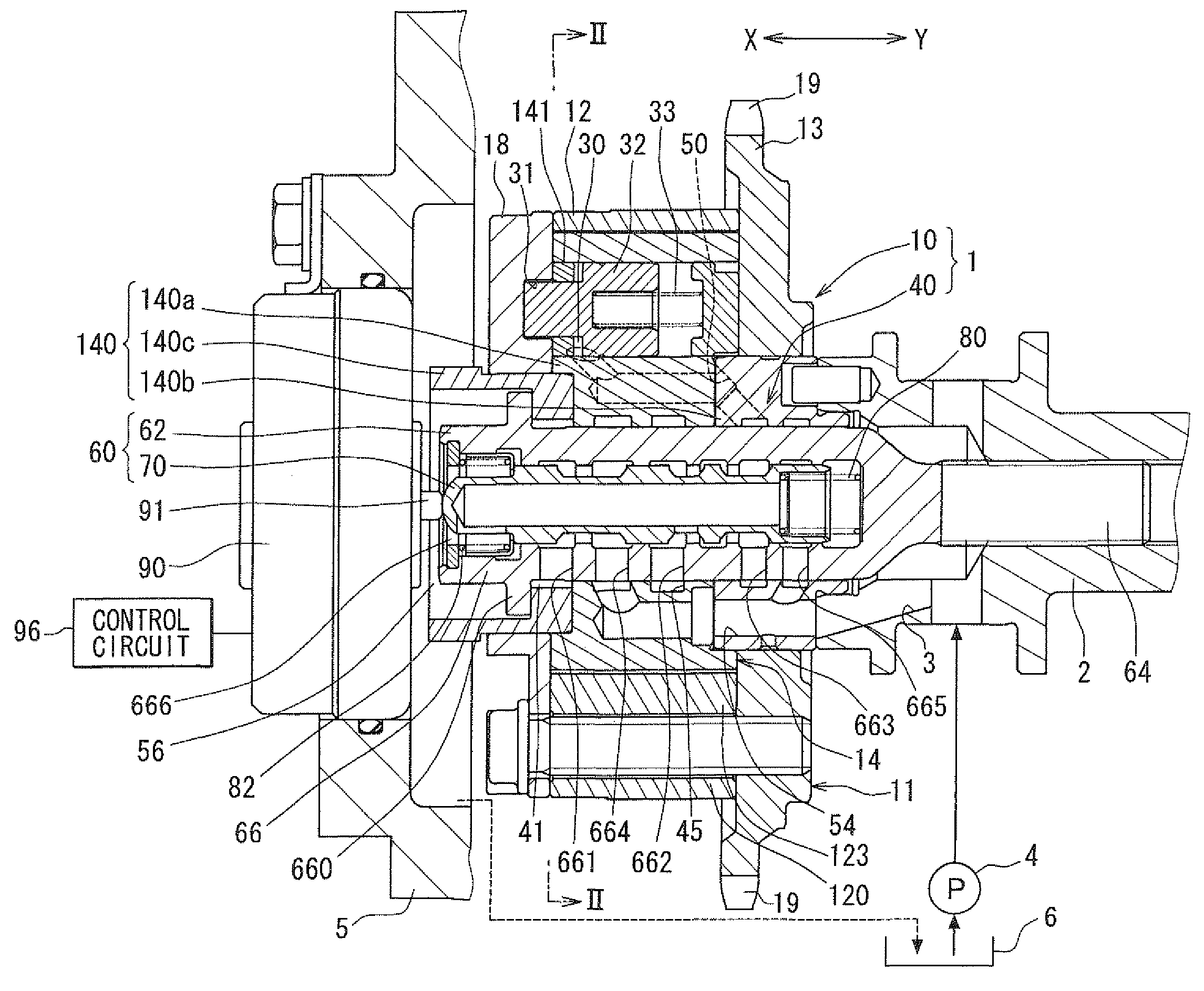
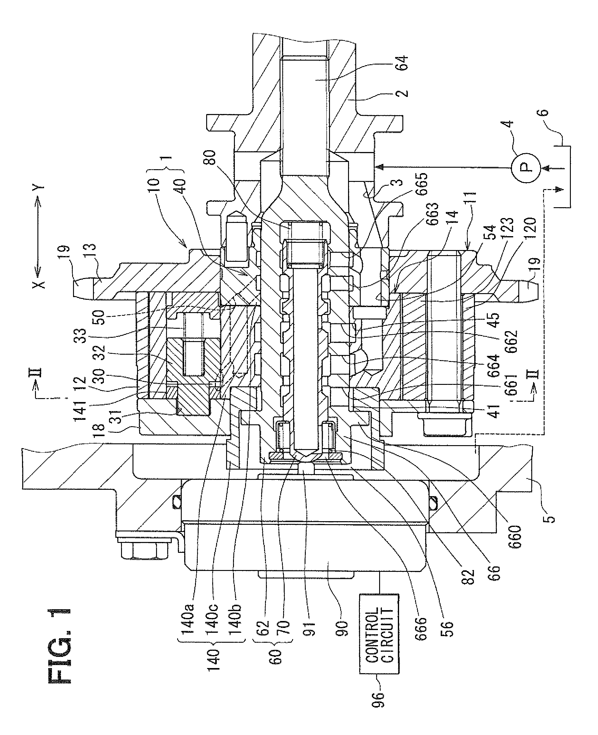
[0036]FIG. 1 shows a first embodiment of a valve timing controller 1 which is applied to an internal combustion engine for a vehicle. The valve timing controller 1 adjusts a valve timing of an intake valve which is driven by a camshaft 2 with hydraulic oil as “hydraulic fluid”. The valve timing adjusting apparatus 1 includes a drive unit 10 and a control unit 40. The drive unit 10 is provided in a driving torque transmission system and is driven with hydraulic oil. The driving torque transmission system transmits a driving torque of a crankshaft (not shown) of an internal combustion engine to a camshaft 2 of the internal combustion engine. The control unit 40 controls supply of hydraulic oil to the drive unit 10.

(Drive Unit)

[0037]A configuration of a drive unit 10 will be described in detail. A housing 11 of the drive unit 10 is comprised of a shoe housing 12, a sprocket 13, a front plate 18 and the like.

[0038]The shoe housing 12 made of metal includes a cylindrical housing body 120...

second embodiment

[0084]A second embodiment shown in FIGS. 11-15 is a modification of the first embodiment. The same parts and components as those in the first embodiment are indicated with the same reference numerals and the same descriptions will not be reiterated. As shown in FIG. 11, a control valve 60 includes a first elastic member 1080, a second elastic member 1082, a movable retainer 1084, a first stopper 1086, and a second stopper 1088.

[0085]The first elastic member 1080 is a coil spring made of metal, which is coaxially disposed in the spool 70 between a second lock land 703 and the movable retainer 1084. The first elastic member 1080 generates a first restoring force biasing the spool 70 and the movable retainer 1084 in the first direction “X” and the second direction “V”.

[0086]The second elastic member 1082 is a coil spring made of metal, which is coaxially disposed in the control valve 60 between a bottom wall of the sleeve 66 and the movable retainer 1084. The second elastic member 1082...


PUM


Abstract

When a spool is positioned in a lock range including a stroke end in a first direction, an advance port and a lock port are respectively connected to a supply port and a discharge port. When the spool is positioned in an advance range deviating from the lock range in a second direction, the advance port and the lock port are fluidly connected to the supply port. While a driving source generates a driving force to move the spool in the second direction, a biasing member biases the spool in the first direction. When the spool is positioned at a limit position of the advance range, a biasing force biasing the spool in the first direction is stepwise varied by a specified variation width.

Description

CROSS-REFERENCE TO RELATED APPLICATION[0001]This application is based on Japanese Patent Application No. 2009-6043 filed on Jan. 14, 2009, the disclosure of which is incorporated herein by reference.FIELD OF THE INVENTION[0002]The present invention relates to a valve timing controller which adjusts a valve timing of a valve by use of hydraulic fluid supplied from a supply source along with an operation of an internal combustion engine. The valve is opened and closed by a camshaft driven by a torque transmitted from a crankshaft of the internal combustion engine.BACKGROUND OF THE INVENTION[0003]A valve timing controller has a housing rotating with a crankshaft and a vane rotor rotating with a camshaft. The housing defines a hydraulic chamber therein. The vane rotor has a vane which divides the hydraulic chamber in a rotational direction. A rotational phase of the vane rotor relative to the housing is varied by introducing hydraulic fluid into the hydraulic chamber. JP-2004-108370A, w...

Claims


Application Information

Patent Timeline
Patent Type & Authority Applications(United States)
IPC IPC(8): F01L1/34
CPCF01L1/022F01L1/3442F01L2001/34469F01L2001/34433F01L2001/3443
Inventor TAKENAKA, AKIHIKO
Owner DENSO CORP
Why Eureka
Try Eureka