Method and apparatus for multi-functional capillary-tube interface unit for evaporation, humidification, heat exchange, pressure or thrust generation, beam diffraction or collimation using multi-phase fluid

a multi-functional, capillary tube technology, applied in the direction of indirect heat exchangers, heat transfer modification, lighting and heating apparatus, etc., can solve the problems of excessive liquid dryout, unacceptable overall system pressure or temperature differences,

Inactive Publication Date: 2010-07-15
GRATTON LUCA JOSEPH
View PDF64 Cites 15 Cited by
  • Summary
  • Abstract
  • Description
  • Claims
  • Application Information

AI Technical Summary

Benefits of technology

[0008]Different liquid saturation levels, total and vapor partial pressures are induced or maintained in the apparatus, depending on a desired or optimized functional adaptation. Plumbing and flow network connections throughout the receiver body vary when optimized for a function or performance level. Plumbing may include dedicated micro-ports. The micro-ports are conduits designed to tap fluid at specified locations along the capillary channel. Configuration options, fluid properties control, and regulation of the heating or cooling rate for the system, allow full control of system function and performance level. The system can operate in steady-state, pulsed-transient, or other transient modes, depending on a desired or optimized functional adaptation and the requisite duty cycle.

Problems solved by technology

There are inherent upper bounds to scaling the system up to increasingly larger size associated with loss of capillary phenomena in channels of sufficiently large radii, with the possibility of extensive liquid dryout for heating, and with unacceptable overall system pressure or temperature differences.

Method used


Image

  • Method and apparatus for multi-functional capillary-tube interface unit for evaporation, humidification, heat exchange, pressure or thrust generation, beam diffraction or collimation using multi-phase fluid
  • Method and apparatus for multi-functional capillary-tube interface unit for evaporation, humidification, heat exchange, pressure or thrust generation, beam diffraction or collimation using multi-phase fluid

Examples


Embodiment Construction

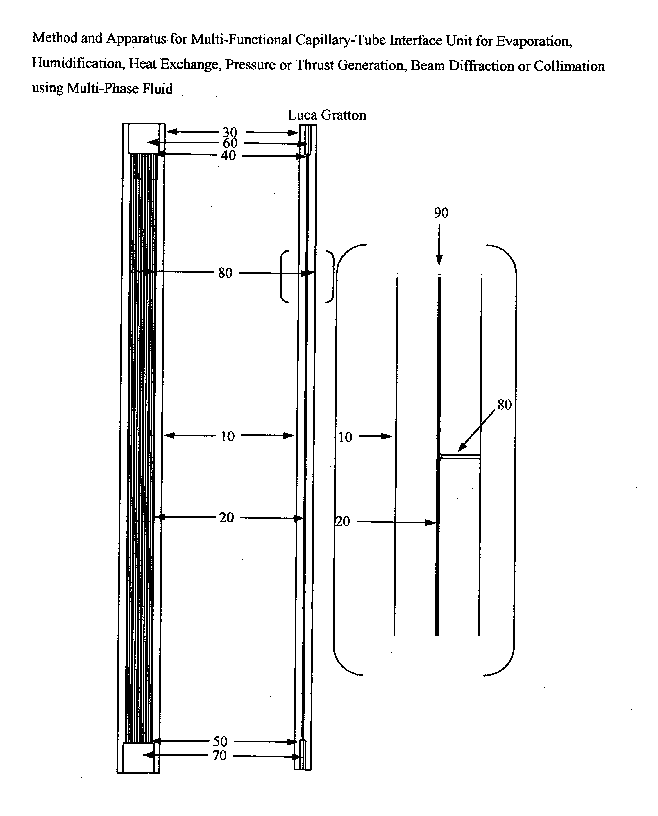
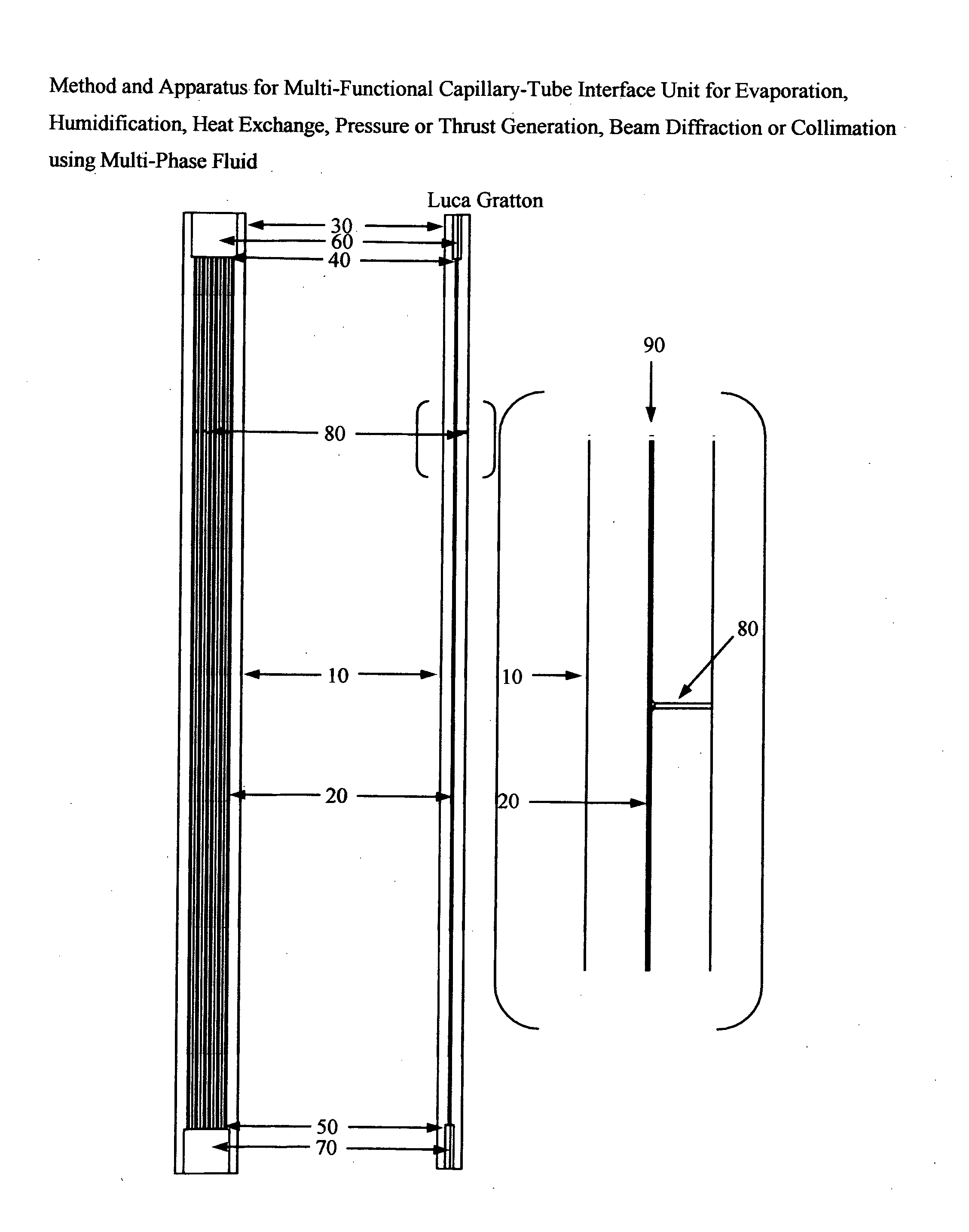
[0019]There is disclosed herein the methods and apparatus of the present invention that uses heat exchange with a volatile fluid in a capillary network to regulate fluid pressure and saturation level at specific locations throughout a miniature device. The volatile fluid may exist as one component in a multi-component fluid mixture. Variations of operational parameters and configuration for the miniature device allow-functional performance in any of eight application modes. These eight application modes are (1) Fluid Evaporator, (2) Fluid Condenser, (3) Gas Phase Humidifier with Working Fluid Vaporization, (4) Single-Stream Heat Exchanger with the Working Fluid, (5) Pressure Generator, (6) Thrust Motor, (7) a Doppler-Shift-Sensitive Fraunhofer Diffraction Device, or (8) a Doppler-Shift-Sensitive Collimation Device.

[0020]The capillary tube network consists of channels with parallel axes that penetrate a solid receiver module 10 (i.e., web) of FIG. 1. The capillary channel walls may f...


PUM


Abstract

A method and apparatus for heat exchange with a volatile fluid in a parallel-channel capillary network traversing a solid receiver module manifests a multi-functional miniature device capable of performing as an evaporator, a condenser, a humidifier, a single-stream heat exchanger, a pressure generator, a thrust motor, a Fraunhofer diffraction device, or a collimation device. Heat is exchanged at a dedicated interface on the body by thermal contact or radiative fluence, and indirectly with the working fluid. Application-specific process control is manifested by applied heat rate, control of fluid saturation levels and vapor partial pressure at the capillary ends, and arrangement of flow network connections. The system operates in steady-state or transient modes, depending on the adapted functional mode and duty cycle. Specific materials and working fluids tolerate transient system performance levels of apparent heat rates exceeding 10 [MW / m3] and local fluid pressures exceeding 1 [GPa].

Description

CROSS-REFERENCE TO RELATED APPLICATIONS[0001]This application claims the benefit and priority of U.S. Provisional Application Ser. No. 61 / 205,101 filed Jan. 15, 2009, by the present inventor, and entitled “Method And Apparatus For Multi-Functional Capillary-Tube Interface Unit For Evaporation, Humidification, Heat Exchange, Pressure Or Thrust Generation, Beam Diffraction Or Collimation Using Multi-Phase Fluid,” which is incorporated herein by reference in its entirety.BACKGROUND OF THE INVENTION[0002]The present invention allows the local heating (or cooling) of a volatile fluid while resident in a capillary tube network consisting of parallel channels penetrating a solid receiver module (i.e., web). The web provides the necessary mechanical structural integrity, and contributes to heat transfer by conductive mode from a heated interface to points throughout the body. Heat is delivered to the heating interface by direct thermal contact, indirect thermal contact, or a radiative fluen...

Claims


Application Information

Patent Timeline
Patent Type & Authority Applications(United States)
IPC IPC(8): F28D15/00F28F9/02
CPCF28F13/187F28D15/046
Inventor GRATTON, LUCA JOSEPH
Owner GRATTON LUCA JOSEPH
Why Eureka
Try Eureka