Tunnel magnetoresistive thin film and magnetic multilayer film formation apparatus

Inactive Publication Date: 2010-07-15
CANON ANELVA CORP
View PDF19 Cites 24 Cited by
  • Summary
  • Abstract
  • Description
  • Claims
  • Application Information

AI Technical Summary

Benefits of technology

[0062]In the tunnel magnetoresistive thin film according to the present invention, the MR ratio does not fall even if the NiFe alloy having the negative magnetostriction is layered on the CoFiFeB magnetization free layer to reduce the magnetostriction despite use of the CoFiFeB magnetization free layer having the positive magnetostriction so as to obtain the high MR ratio. Accordingly, it is possible to provide the tunnel magnetoresistive thin film having both the high MR ratio and the low magnetostriction, and to ensure go

Problems solved by technology

In the conventional tunnel magnetoresistive thin film using amorphous CoFeB as the ferromagnetic electrode and MgO of the NaCl structure as the tunnel barrier layer, a magnetization free layer is a COFeB monolayer having a large positive magnetostriction, which causes noise when a device operates.
In the conventio

Method used


Image

  • Tunnel magnetoresistive thin film and magnetic multilayer film formation apparatus
  • Tunnel magnetoresistive thin film and magnetic multilayer film formation apparatus
  • Tunnel magnetoresistive thin film and magnetic multilayer film formation apparatus

Examples


Example

Example 1

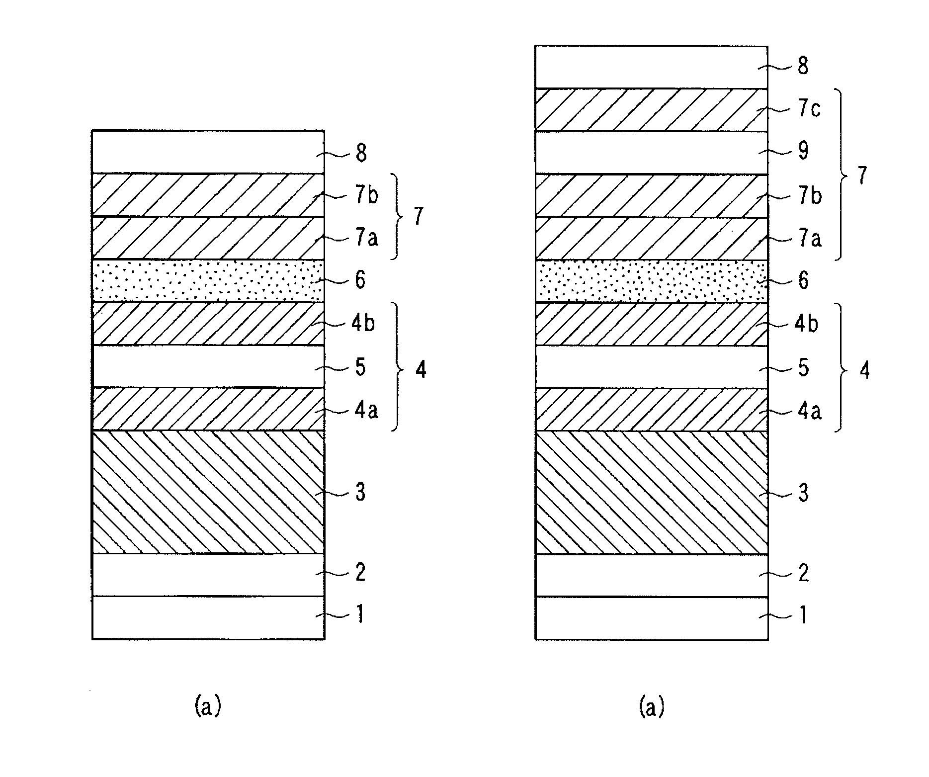
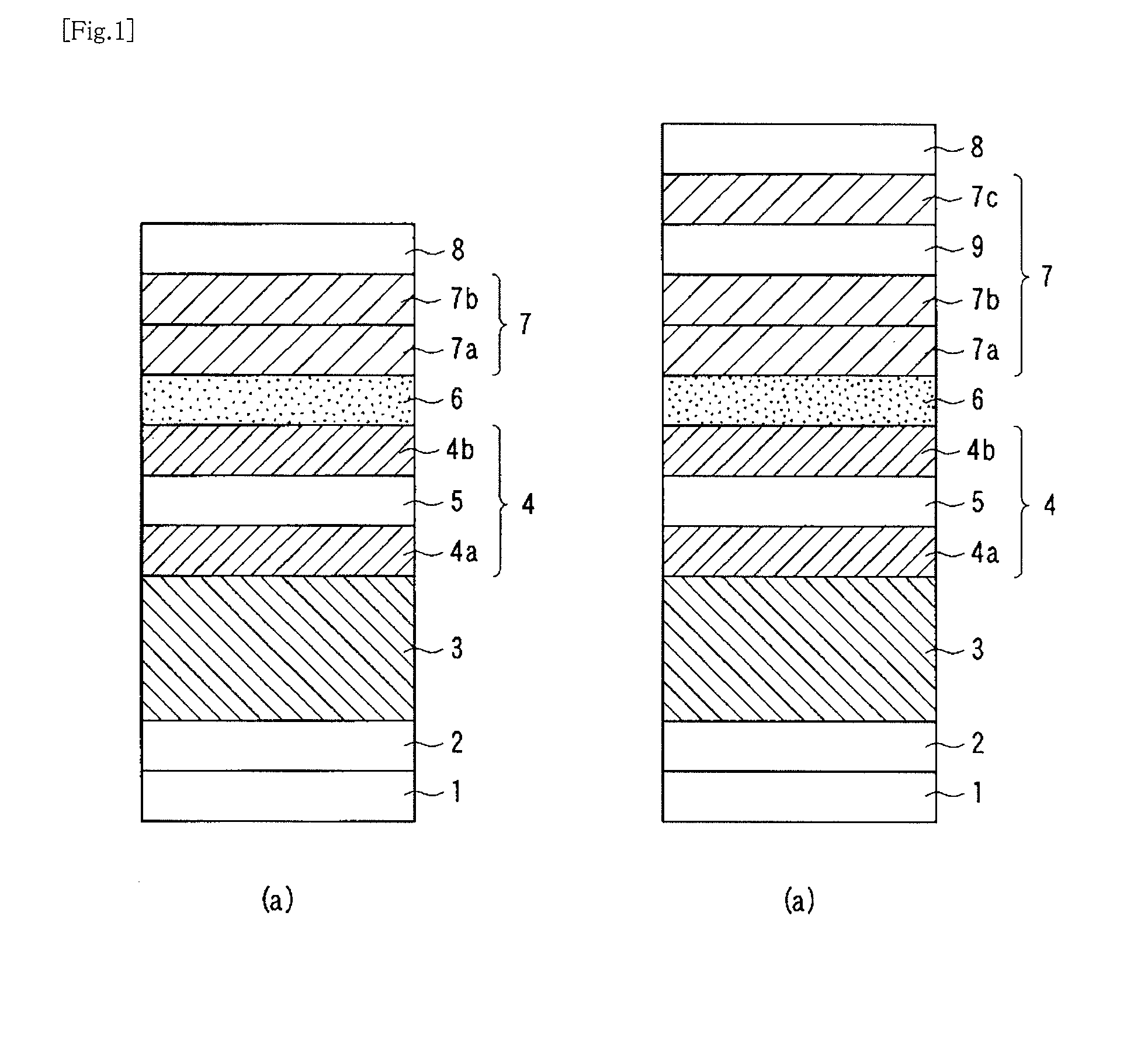
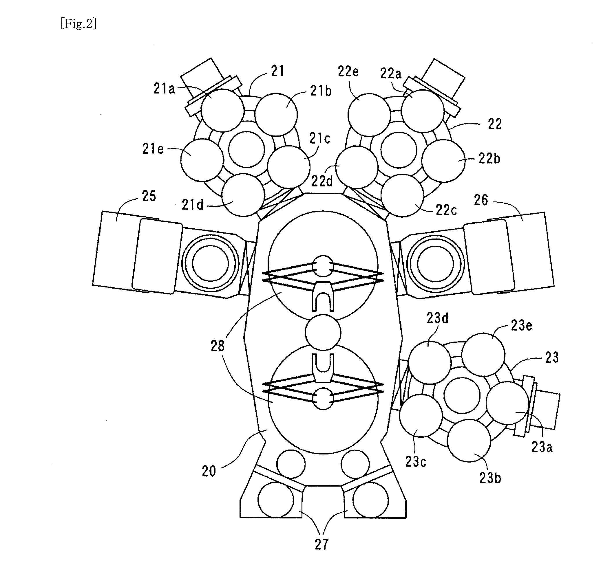
[0154]The bottomed spin-valve tunnel magnetoresistive thin film having the film configuration shown in FIG. 1(a) was produced using the device shown in FIG. 2. In Example 1, the buffer layer 2 was Ta (10 nm), the antiferromagnetic layer 3 was PtMn (15 nm), the magnetization fixed layer 4 was the layered ferrimagnetic fixed layer configured to include CoFe (2.5 nm) / Ru (0.85 nm) / CoFeB (3 nm), and the tunnel barrier layer 6 was MgO (15 nm). Furthermore, as the magnetization free layer 7, a CoNiFe film having the body-centered cubic structure in a state of being formed was formed first and a NiFe film having the face-centered cubic structure was then formed. As the protection layer 8, a layered structure of Ta (10 nm) / Ru (7 nm) was used.

[0155]Moreover, (Co70Fe30)96B4 was used as the first magnetization free layer 7a and Ni83Fe17 containing 83 atomic % of Ni and having the face-centered cubic structure was used as the second magnetization free layer 7b. Further, magnetoresistive...

Example

Example 2

[0168]The bottomed spin-valve tunnel magnetoresistive thin film having the film configuration shown in FIG. 1(b) was manufactured. In Example 2, samples were similar to those in Example 1 except that an Ru film (2 nm) was layered as the exchange-coupling nonmagnetic layer 9 on the magnetization free layer including the CoNiFeB / NiFe films similar to each sample in Example 1 according to the present invention, and that a NiFe film (3 nm) was then layered as the magnetization free layer 7c on the exchange-coupling nonmagnetic layer 9.

[0169]Each of obtained magnetoresistive thin films exhibited improved heat resistance as well as a high MR ratio and low magnetostriction similarly to Example 1.

Example

Example 3

[0170]The bottomed spin-valve tunnel magnetoresistive thin films using the samples according to the present invention similarly to Example 1 except that the magnetization fixed layer 4 was amorphous CoFeB (3 nm) were manufactured.

[0171]Each of obtained magnetoresistive thin films exhibited improved heat resistance as well as a high MR ratio and low magnetostriction similarly to Example 1.


PUM


Abstract

A tunnel magnetoresistive thin film which can simultaneously realize a high MR ratio and low magnetostriction is provided.
The tunnel magnetoresistive thin film comprises a magnetization fixed layer, a tunnel barrier layer, and a magnetization free layer, wherein the tunnel barrier layer is a magnesium oxide film containing magnesium oxide crystal grains and the magnetization free layer is a layered structure including a first magnetization free layer and a second magnetization free layer, the first magnetization free layer being made of alloy containing Co atoms, Fe atoms, and B atoms or containing Co atoms, Ni atoms, Fe atoms, and B atoms, having a body-centered cubic structure, and having (001) orientation, the second magnetization free layer being made of alloy containing Fe atoms and Ni atoms and having a face-centered cubic structure.

Description

TECHNICAL FIELD[0001]The present invention relates to a tunnel magnetoresistive thin film used in a magnetic reproducing head of a magnetic disk drive, a storage element of a magnetic random access memory or in a magnetic sensor, and a magnetic multilayer film formation apparatus.BACKGROUND ART[0002]A tunnel magnetoresistive thin film using amorphous CoFeB as a ferromagnetic electrode and MgO of a NaCl structure as a tunnel barrier layer exhibits quite a high MR ratio (magnetoresistance change ratio) equal to or higher than 200% at room temperature. Due to this, the tunnel magnetoresistive thin film is expected to be applied to a magnetic reproducing head of a magnetic disk drive, a storage element of a magnetic random access memory (MRAM) or a magnetic sensor. In the conventional tunnel magnetoresistive thin film using amorphous CoFeB as the ferromagnetic electrode and MgO of the NaCl structure as the tunnel barrier layer, a magnetization free layer is a COFeB monolayer having a la...

Claims


Application Information

Patent Timeline
IPC IPC(8): G11B5/39
CPCB82Y10/00Y10T428/1114B82Y40/00G01R33/093G01R33/098G11B5/3906G11B5/3909G11C11/15G11C11/16H01F10/16H01F10/3254H01F41/302H01L27/228H01L43/08H01L43/10H01F10/3295Y10T428/1121B82Y25/00G11C11/161H10B61/22H10N50/85H10N50/10H01F10/32G01R33/09H10B99/00
Inventor TSUNEKAWA, KOJINAGAMINE, YOSHINORI
Owner CANON ANELVA CORP
Why Eureka
Try Eureka