Hybrid vehicle power transmission device and hybrid vehicle

a hybrid vehicle and power transmission technology, applied in the direction of electric propulsion mounting, transportation and packaging, gearing, etc., can solve the problems of increasing the size of the damper device, and achieve the effect of reducing the size of the devi

Active Publication Date: 2010-07-15
TOYOTA JIDOSHA KK
View PDF4 Cites 13 Cited by
  • Summary
  • Abstract
  • Description
  • Claims
  • Application Information

AI Technical Summary

Benefits of technology

[0007]The invention provides a hybrid vehicle power transmission device provided with a power distribution mechanism composed of a planetary gear device for distributing motive power of a drive source to a motor and output shaft that enables the size of the device to be reduced, and a hybrid vehicle equipped with a hybrid vehicle power transmission device that enables the size of the device to be reduced.
[0009]According to the hybrid vehicle power transmission device as claimed in the first aspect of the invention, since a damper device is provided in the power transmission path between the power distribution mechanism and the motor, direct transmission of drive torque of the drive source is avoided. More specifically, as a result of being composed in the manner described above, the damper device receives only reaction torque dealt by the motor through the power distribution mechanism with respect to drive torque of the drive source. Thus, since the torque transmitted to the damper device is smaller than the drive torque of the drive source, the torque capacity of the damper device can be decreased, and as a result, the size of the damper device can be reduced. Consequently, the overall size of the power transmission device can be similarly reduced.
[0011]According to the hybrid vehicle as claimed in the second aspect of the invention, the size of a damper device can be reduced due to the effects of the first aspect of the invention. Thus, the overall size of the power transmission device can be similarly reduced. Moreover, the space for installing the power transmission device in the hybrid vehicle is easily secured.

Problems solved by technology

Thus, since it becomes necessary to increase the torque capacity of the damper device, the size of the damper device increases.
Thus, the problem of increasing size of the power transmission device arose accompanying increased size of the damper device in this manner.

Method used


Image

  • Hybrid vehicle power transmission device and hybrid vehicle
  • Hybrid vehicle power transmission device and hybrid vehicle
  • Hybrid vehicle power transmission device and hybrid vehicle

Examples


Embodiment Construction

[0017]Here, the damper device may further include a torque limiter mechanism. If a torque limiter mechanism is so included, torque fluctuations of the drive source can be absorbed and malfunctions caused by excessive torque input to the damper device can be avoided.

[0018]The following provides a detailed explanation of embodiments of the invention with reference to the drawings. Furthermore, drawings of the embodiments may be suitably simplified or altered, and dimensional ratios, shapes and the like of each component are not necessarily depicted accurately.

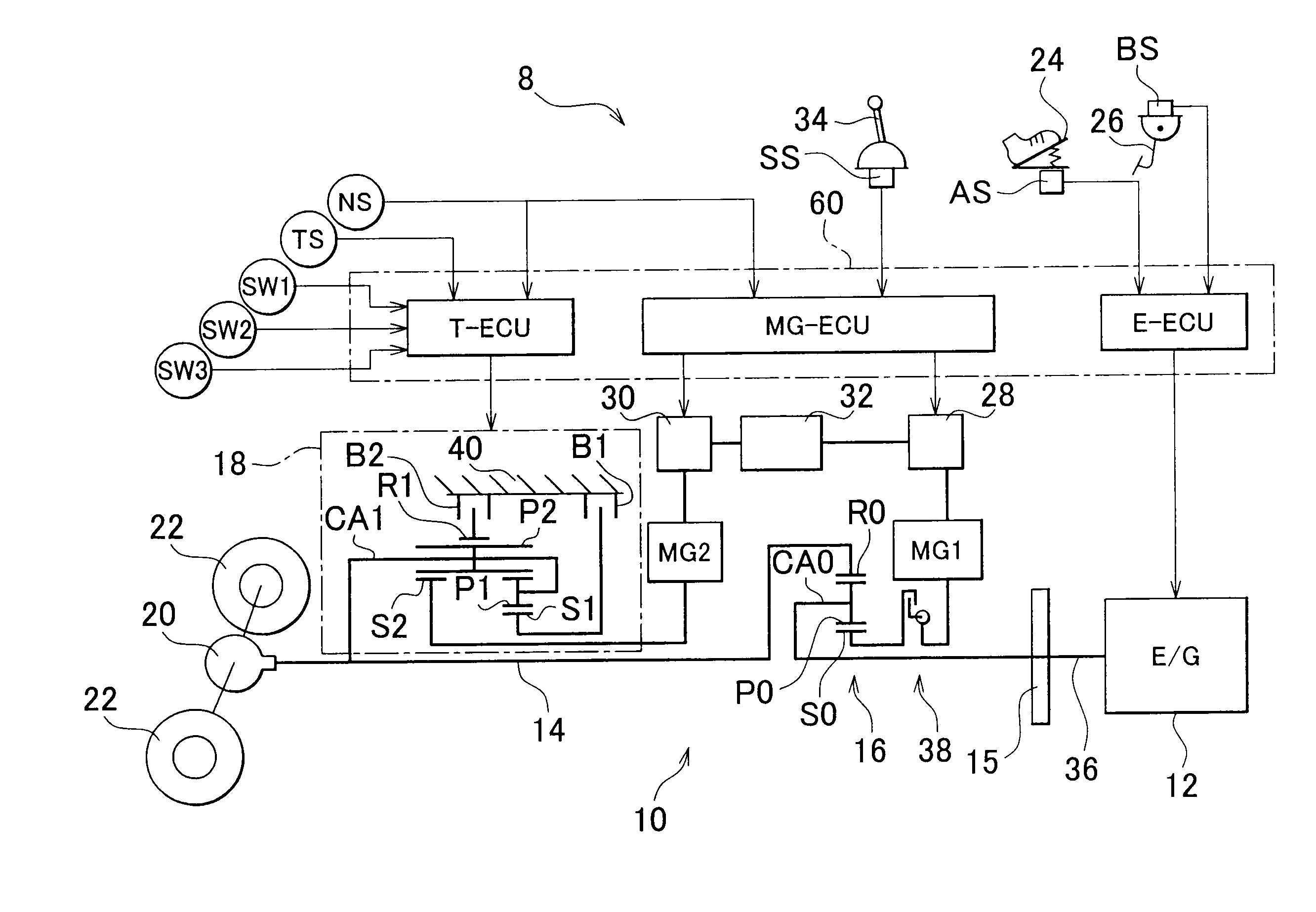
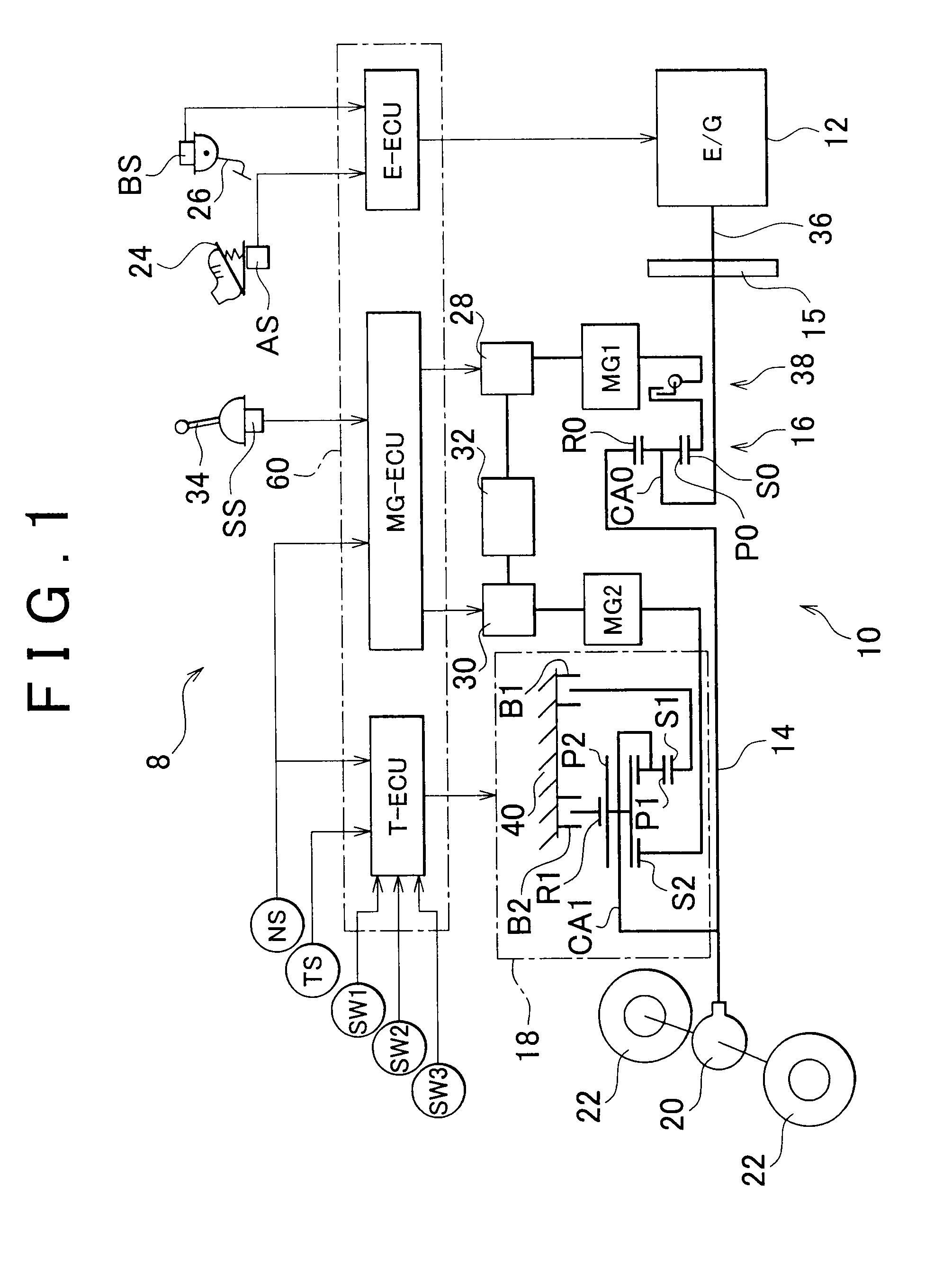
[0019]FIG. 1 is a drawing for explaining a hybrid vehicle 8 in which the invention is applied. The hybrid vehicle 8 shown in FIG. 1 is composed by being provided with a hybrid vehicle power transmission device (to be simply referred to as a power transmission device) 10 having a power distribution mechanism 16, which distributes motive power output from a main power source in the form of an engine 12 (equivalent to the drive sour...


PUM


Abstract

A hybrid vehicle power transmission device provided with a power distribution mechanism composed of a planetary gear device for distributing motive power of a drive source to a motor and an output shaft is further provided with a damper device in a power transmission path between the power distribution mechanism and a first motor. Consequently, the damper device receives only reaction torque dealt by the first motor through the power distribution mechanism with respect to drive torque of an engine. Thus, since the torque transmitted to the damper device is smaller than the drive torque of the engine, the torque capacity of the damper device can be decreased and the size of the damper device can be reduced. As a result, the overall size of the power transmission device can be similarly reduced.

Description

INCORPORATION BY REFERENCE[0001]The disclosure of Japanese Patent Application No. 2009-005334 filed on Jan. 14, 2009, including the specification, drawings and abstract, is incorporated herein by reference in its entirety.BACKGROUND OF THE INVENTION[0002]1. Field of the Invention[0003]The invention relates to a hybrid vehicle power transmission device and a hybrid vehicle, and more particularly to the reduction in size of a power transmission device.[0004]2. Description of the Related Art[0005]Hybrid vehicle power transmission devices, provided with a drive source, and a power distribution mechanism composed of a planetary gear device for distributing motive power of the drive source to a motor and an output shaft, are commonly known. The hybrid vehicle described in Japanese Patent Application Publication No. 2002-225578 (JP-A-2002-225578) is one example thereof. In the hybrid vehicle described in JP-A-2002-225578, a carrier of a power distribution mechanism (planetary gear mechanis...

Claims


Application Information

Patent Timeline
Patent Type & Authority Applications(United States)
IPC IPC(8): F16H3/72B60L50/16
CPCB60K1/02Y02T10/642B60K6/445B60K6/547B60L2240/423B60W10/06B60W10/08B60W20/00B60W2710/0666B60W2710/083F16H3/728F16H2037/101F16H2200/2007F16H2200/2023F16H2200/2035Y02T10/6239Y02T10/6286B60K6/365Y02T10/62Y02T10/64B60W20/40
Inventor KUZUYA, TETSUROIBARAKI, RYUJIODAKA, KENJIIWASE, YUJITAKENAKA, TATSUSHIMARUYAMA, TOMOYUKIKONDO, KOICHI
Owner TOYOTA JIDOSHA KK
Why Eureka
Try Eureka