Optical film and process for producing the same

a technology of optical film and process, applied in the field of optical film, can solve the problems of unevenness and concave convexity of the film, the quality of the film becomes deteriorated, and the above requirements for qualities become more severe, so as to achieve efficient production of optical film, good flatness, and low cost of cleaning the rotating member

Inactive Publication Date: 2010-07-15
KONICA MINOLTA OPTO
View PDF1 Cites 5 Cited by
  • Summary
  • Abstract
  • Description
  • Claims
  • Application Information

AI Technical Summary

Benefits of technology

[0023]Even for the material of the optical film containing 5% by weight or more of additive agent other than resin, the invention described in claim 1 can provide the effects that there is no pollution on the rotating member by an additive agent etc., the cost of the cleaning of the rotating member becomes very cheap, and it becomes possible to produce efficiently an optical film which has a good flatness and an excellent optical characteristic. If the temperature of the first rotating member for cooling is made more than the glass transition temperature (Tg) of the resin mixture, when the resin mixture is separated from the first rotating member for cooling, separation unevenness occurs. Further, if the temperature of the first rotating member for cooling is made less than the melting point of the additive agent, it is not desirable, because the additive agent having volatilized from the film is solidified on a rotating member, pollutes the rotating member, is transferred to a film and appears as stains on the film. It is more desirable that the temperature of the first rotating member for cooling is made equal to or less than (the glass transition temperature (Tg) of the resin mixture −5° C.) and equal to or more than (the melting point of the additive agent 5° C.).
[0024]The invention described in claim 2 is made, in the optical film producing method described in claim 1, such that the ratio (S3 / S1) of the peripheral speed (S1) of the peripheral speed (S3) of the third rotating member for cooling to the first rotating member for cooling is 1.001 to 1.05. Therefore, the invention described in claim 2 can provide the effects that there is no pollution on the rotating member by an additive agent etc., the cost of the cleaning of the rotating member becomes very cheap, and it becomes possible to produce efficiently an optical film which has a good flatness and an excellent optical characteristic.
[0025]If the ratio (S3 / S1) of the peripheral speed of the rotating member is less than 1.001, since the adhesiveness between the rotating member and the film becomes worse, pollution by the additive agent may occur on the rotating member. On the other hand, if the ratio (S3 / S1) of the peripheral speed of the rotating member exceeds 1.05, it is not desirable, because the flatness of the film being conveyed currently may be spoiled, stains may take place on the rotating member and the film, or the film may break out. The ratio (S3 / S1) of the peripheral speed of the rotating member is 1.002 to 1.04 more desirably, and 1.005 to 1.03 most desirably.
[0026]The invention described in claim 3 is made, in the optical film producing method described in claim 1 or 2, such that the film-shaped molten mixture is pressed onto the first rotating member for cooling with a line pressure of 0.5 to 50 N / mm by the second rotating member for pressing. Therefore, the invention described in claim 3 can provide the effects that the film-shaped molten mixture can be brought sufficiently in close contact with the first rotating member for cooling, it is possible to prevent pollution on the rotating member by an additive agent etc. beforehand, the effect in cleaning the rotating member becomes high, and it becomes possible to produce efficiently an optical film which has a good flatness and an excellent optical characteristic. If the line pressure of the second rotating member for pressing is less than 0.5 N / mm, it is not desirable, because the film is not pressed sufficiently between the first rotating member for cooling and the second rotating member for pressing, and if a portion incapable of being pressed partially takes place, the portion may become the source of pollution. If the line pressure of the second rotating member for pressing exceeds 50 N / mm, it is not desirable, because distortion takes place on the film so as to make the additive agent stand out on the surface of the film, the stand-out additive agent adheres on the rotating member, and the adhered additive agent becomes the source of pollution. In the present invention, the line pressure of the second rotating member for pressing is 0.7 to 40 N / mm preferably, and 1 to 30 N / mm more preferably.
[0027]The invention described in claim 4 is made, in the optical film producing method described in any one of claims 1 to 3, such that the resin mixture contains additive agent other the resin in an amount of 5% by weight or more and 20% by weight or less. Therefore, the invention described in claim 4 can provide the effects that there is no pollution on the rotating member by an additive agent etc., and it becomes possible to produce efficiently an optical film which has a good flatness and an excellent optical characteristic.
[0028]In the present invention, the additive agent is defined as one which is contained in an amount of 0.3% by weight or more in the film. In the present invention, the additive agent is a plasticizer and an ultraviolet absorber, for example.

Problems solved by technology

In particular, since a monitor or a TV become larger and higher definition, the above requirements for qualities becomes more severe.
However, the melt casting film producing method has the following drawbacks.
If the pollution advances, the pollution is transferred onto a film to cause spotty unevenness and concavo-convex on the film.
As a result, the quality of a film becomes deteriorated.
Further, when rollers become dirty, a film production is obliged to be interrupted due to the cleaning of the rollers.

Method used


Image

  • Optical film and process for producing the same
  • Optical film and process for producing the same
  • Optical film and process for producing the same

Examples


example 1

[0319]

(Resin mixture)Cellulose acetate propionate  89 weight %(the degree of acetyl group substitution: 1.4, thedegree of propionyl group substitution: 1.35,number average molecular weight: 60000)Trimethylolpropane tribenzoate  9 weight %(Plasticizer, a melting point of 85° C.)Antioxidant (IRGANOX XP 420 / FD)0.25 weight %(manufactured by Ciba Speciality Chemicals Corp.)Ultraviolet absorber 1.6 weight %(TINUVIN 928, manufactured by Ciba SpecialityChemicals Corp., a melting point of 115° C.)Matting agent (silica particle)0.15 weight %(SEAHOSTAR KEP-30: manufactured by NIPPONSHOKUBAI Co., Ltd., average particle diameterof 0.3 μm)

[0320]Here, the measurement of a degree of substitution of acyl groups of cellulose acetate propionate, such as an acetyl group, a propionyl group, and a butyryl group, was conducted in accordance with the method specified in ASTM-D 817-96.

[0321]After above-mentioned materials were mixed by a V shaped mixer for 30 minutes, the resultant mixture was melted at 230...

examples 2 to 11

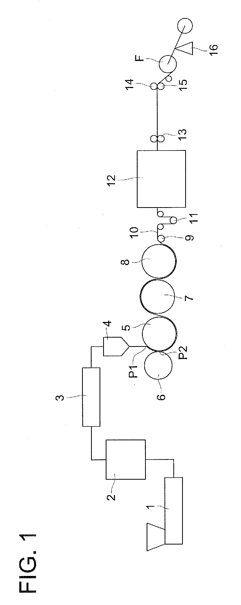
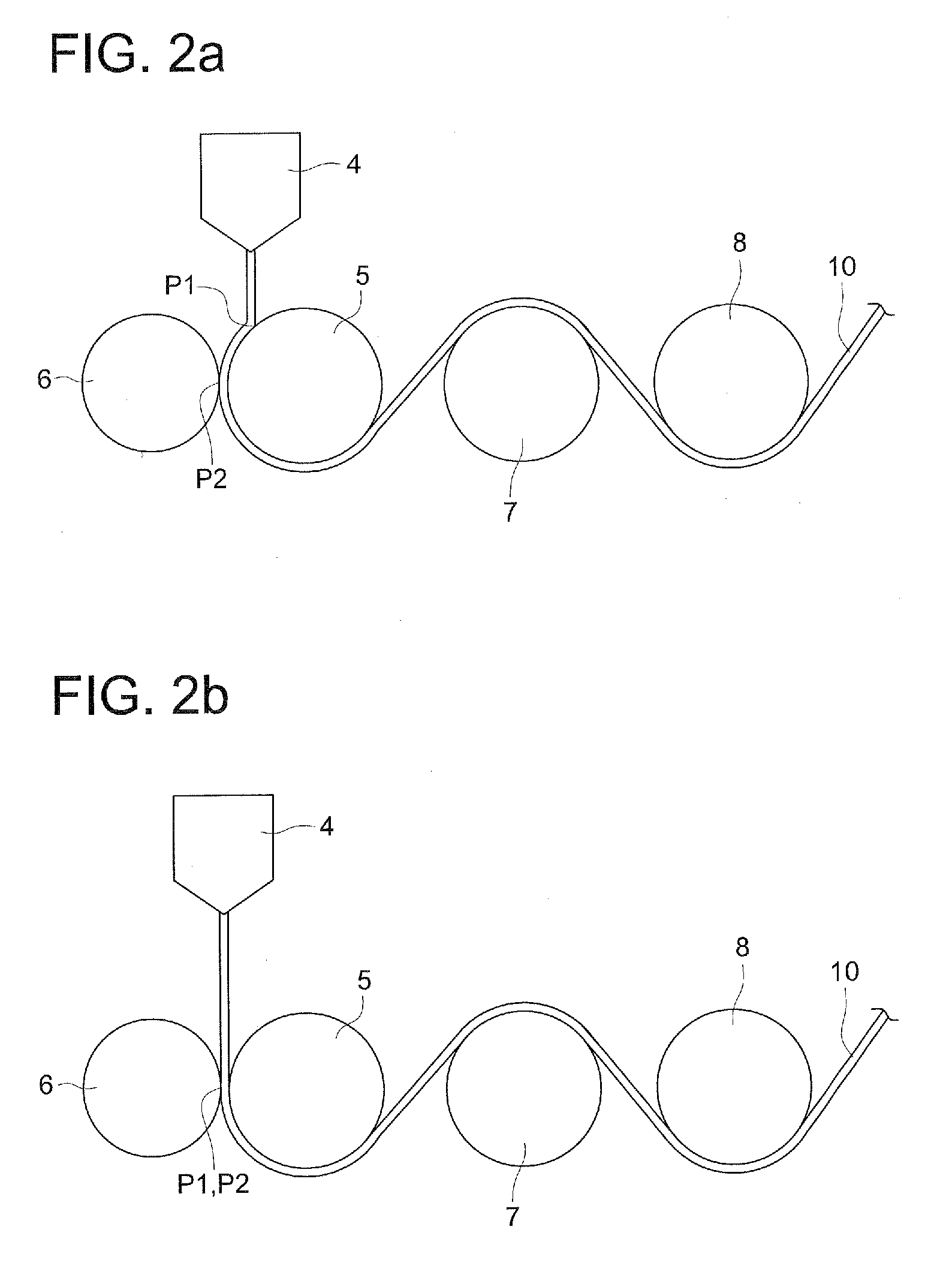
[0329]In Examples 2 to 11, cellulose acetate propionate films were produced in the same way as that in Example 1. However, cellulose acetate propionate films were produced in such a way that while the surface temperature of the first cooling roller (first rotating member for cooling) 5 was set within the range of the present invention, the line pressure of the touch roller (second rotating member for pressing) 6 and the ratio (S3 / S1) between the peripheral velocity (S1) of the first cooling roller (first rotating member for cooling) 5 and the peripheral velocity (S3) of the second cooling roller (third rotating member for cooling) 7 were changed variously.


PUM

PropertyMeasurementUnit
Tgaaaaaaaaaa
transparencyaaaaaaaaaa
weightaaaaaaaaaa

Abstract

An optical film of high planarity that even in the use of an optical film material containing a non-resinous additive in an amount of 5 mass % or more, would exhibit inexpensive satisfactory roll cleaning effects, and that would find application in, especially, various functional films such as a retardation film and a protective film for polarization plate for use in a liquid crystal display apparatus, etc.; and a process for producing the optical film. There is disclosed a process for producing an optical film according to a melting casting film forming method, including extruding a melt of resin blend containing a resin and 5 mass % or more of non-resinous additive through a casting die into a film form, wherein a first roller (5) for cooling has a temperature of the melting point of the additive to the glass transition temperature (Tg) of the resin blend. Preferably, the first roller (5) for cooling has a peripheral speed (S1) exhibiting a ratio between the same and the peripheral speed (S3) of a third roller (7) for cooling, S3 / S1, of 1.001 to 1.05. Preferably, a filmlike molten blend is pressed against the first roller (5) for cooling at a linear pressure of 0.5 to 50 N / mm by means of a second roller (6) for pressure application.

Description

TECHNICAL FIELD[0001]The present invention relates to an optical film with a high flatness that is produced by a melt casting film forming method, and, in particular, relates to an optical film capable of being utilized for a polarizing plate protection film, a retardation film and a view angle expanding film for use in a liquid crystal display device, further for various kinds of functional film such as an antireflection film for use in a plasma display, as well as for various kinds of functional film for use in an organic EL display and the like. Further, the present invention relates to a method of manufacturing these films.BACKGROUND ART[0002]In a liquid crystal display, various kinds of optical films, such as a polarization film and a retardation film, are used. In a polarization film of a polarizing plate for use in a liquid crystal display, a cellulose ester film is laminated as a protection film on one side or both sides of a polarizer composed of a stretched polyvinyl alcoh...

Claims


Application Information

Patent Timeline
Patent Type & Authority Applications(United States)
IPC IPC(8): C08K5/12B29D11/00B29C48/08B29C48/305B29C48/355B29C48/91B29C48/92
CPCB29C47/0021B29C47/0057B29C47/34B29C47/8845B29C47/886B29C47/92B29L2031/3475B29C2947/92923B29K2105/0005B29K2105/256B29K2995/0018B29K2995/0072B29L2011/00B29C2947/92704B29C48/91B29C48/918B29C48/9185B29C48/914B29C48/08B29C48/92B29C48/9155B29C48/0018B29C48/355B29C2948/92704B29C2948/92923
Inventor HEKI, KATSUHIKO
Owner KONICA MINOLTA OPTO
Why Eureka
Try Eureka