
Tissue roll scaffolds

a tissue roll and scaffold technology, applied in the field of tissue engineering, can solve the problems of increasing complexity in the temporal patterning and interrelationships between each component of the response, affecting the ability to add individual and complicating the ability to add exogenous factors at the proper tim

Inactive Publication Date: 2010-07-15
KCI LICENSING INC
View PDF100 Cites 100 Cited by
  • Summary
  • Abstract
  • Description
  • Claims
  • Application Information

AI Technical Summary

Benefits of technology

This approach enhances tissue regeneration by actively guiding the healing process, improving the deposition of proteins and cells, and reducing the immunogenic response, leading to more effective tissue repair and remodeling.

Problems solved by technology

The later stages of the wound healing response are dependent upon the previous stages, with increasing complexity in the temporal patterning of and interrelationships between each component of the response.
Although some level of success has been achieved using this approach, several key challenges remain.
One main challenge is that the timing and coordinated influence of each cytokine and growth factor within the wound healing response complicate the ability to add individual exogenous factors at the proper time and in the correct coordination pattern.
The introduction of exogenous cells also faces additional complications due to their potential immunogenicity as well as difficulties in maintaining cell viability.
As such, the colonization of endogenous cells into the scaffold is limited by the distance away from vascular elements, which provide nutrient support within a diffusion limit of the scaffold, regardless of tissue type.
Taken together, these complications can all lead to less than functional tissue regeneration at the implantation or injury site.

Method used


Image

  • Tissue roll scaffolds
  • Tissue roll scaffolds
  • Tissue roll scaffolds

Examples


Embodiment Construction

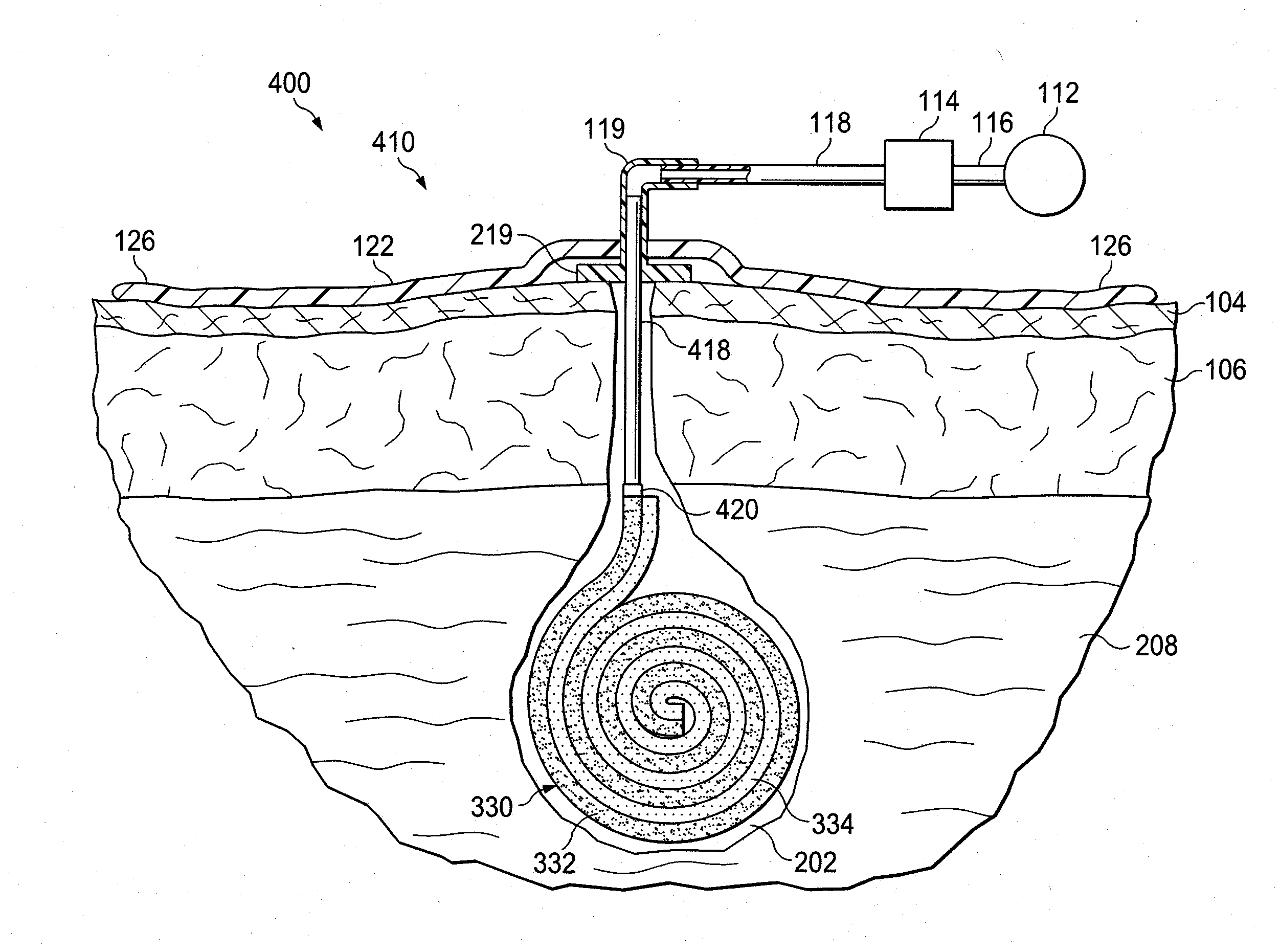
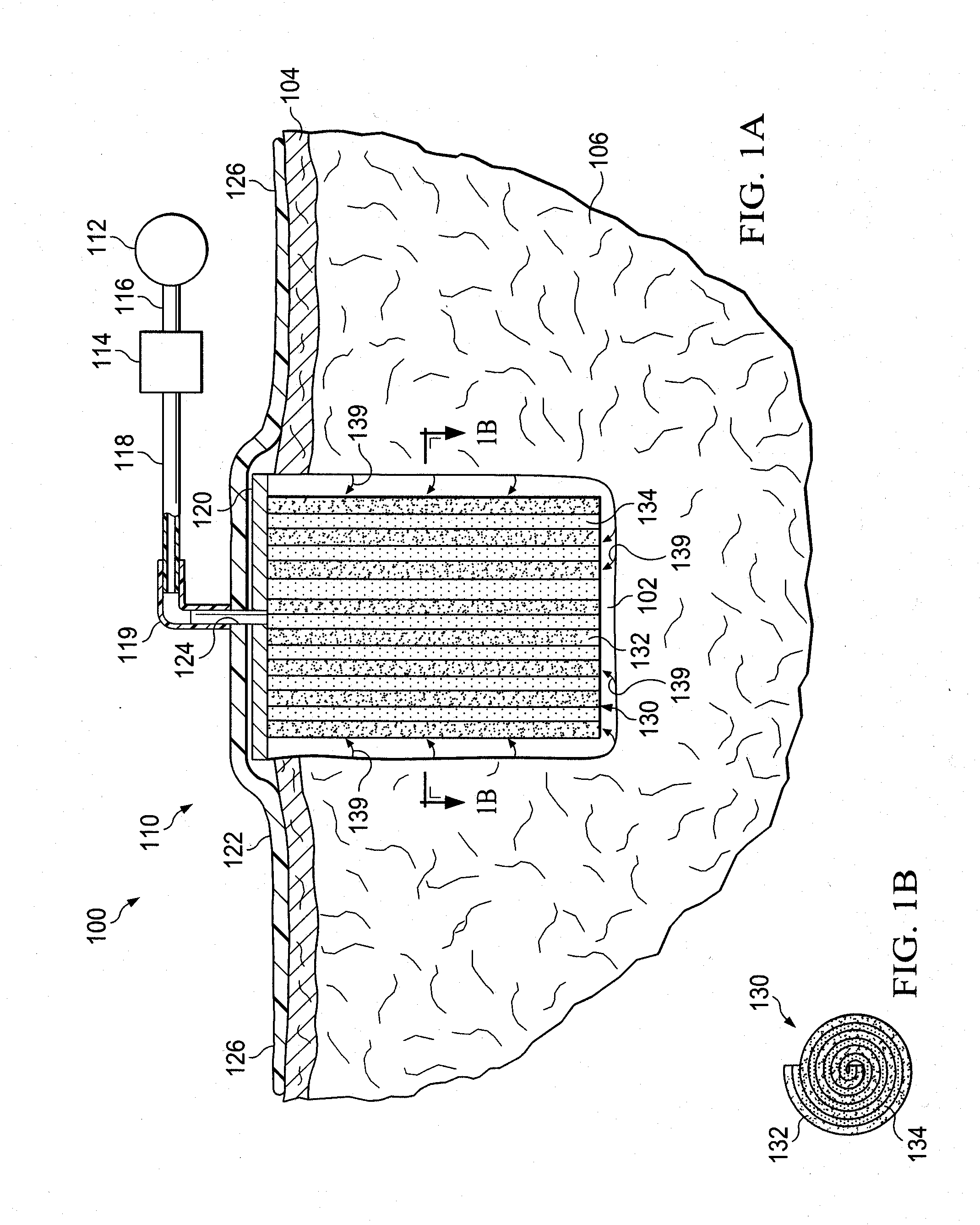
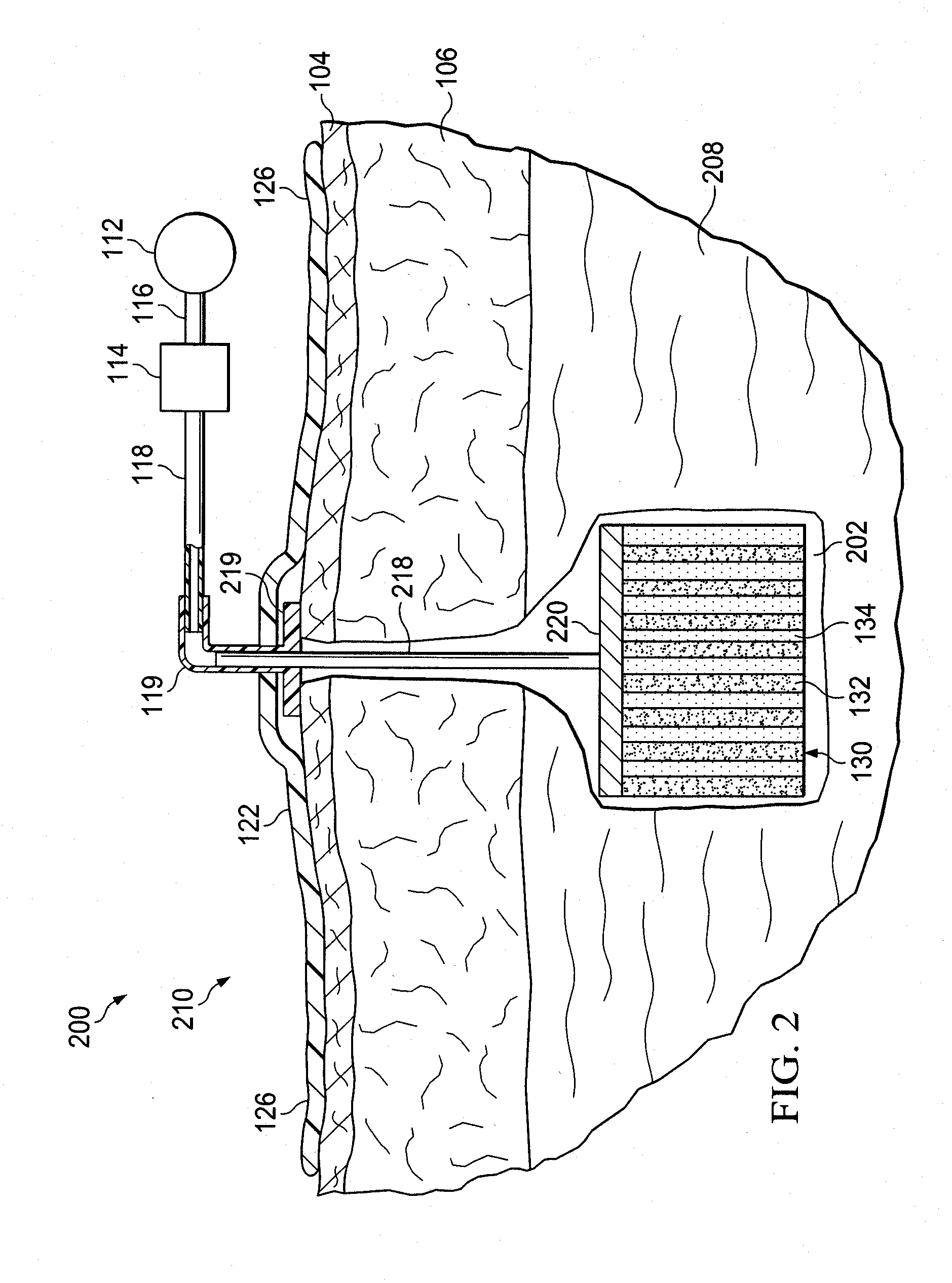
[0021]In the following detailed description of the illustrative embodiments, reference is made to the accompanying drawings that form a part hereof. These embodiments are described in sufficient detail to enable those skilled in the art to practice the invention, and it is understood that other embodiments may be utilized and that logical structural, mechanical, electrical, and chemical changes may be made without departing from the spirit or scope of the invention. To avoid detail not necessary to enable those skilled in the art to practice the embodiments described herein, the description may omit certain information known to those skilled in the art. The following detailed description is, therefore, not to be taken in a limiting sense, and the scope of the illustrative embodiments are defined only by the appended claims.

[0022]The term “reduced pressure” as used herein generally refers to a pressure less than the ambient pressure at a tissue site that is being subjected to treatme...


PUM

PropertyMeasurementUnit
elongation ratesaaaaaaaaaa
pressureaaaaaaaaaa
bioabsorbableaaaaaaaaaa

Abstract

An apparatus and system for treating a wound having a cavity is disclosed. The apparatus comprises a scaffold including a scaffold lamina and a tissue lamina wherein the scaffold lamina forms a laminate in fluid communication with the tissue lamina. The laminate is rolled into a generally cylindrical shape having two end surfaces. The apparatus further comprises a manifold having a port for coupling to a source of reduced pressure and that is positioned in fluid communication with the scaffold to provide reduced pressure to the scaffold lamina and the wound. The apparatus also comprises a drape formed of substantially impermeable material to cover the scaffold and the manifold within the wound. A method for treating a wound having a cavity is also disclosed and comprises positioning a scaffold lamina adjacent a tissue lamina to form a laminate in fluid communication with the tissue lamina, rolling the laminate into a generally cylindrical shape having two end surface, and positioning the scaffold within the cavity of the wound to provide reduced pressure to the wound. The method further comprises positioning a manifold in fluid communication with the scaffold to provide reduced pressure to the scaffold lamina and the wound.

Description

CROSS-REFERENCE TO RELATED APPLICATIONS[0001]This application claims priority to U.S. Provisional Application Nos. 61 / 142,053 and 61 / 142,065, each filed on Dec. 31, 2008. This application also claims priority to U.S. Provisional Application No. 61 / 234,692, filed on Aug. 18, 2009 and U.S. Provisional Application No. 61 / 238,770, filed on Sep. 1, 2009. Each of the foregoing applications is incorporated herein by reference in their entirety.BACKGROUND[0002]1. Field of the Invention[0003]The present application relates generally to tissue engineering and in particular to apparatuses and systems suitable for use as scaffolds in the treatment of wounds.[0004]2. Description of Related Art[0005]Clinical studies and practice have shown that providing a reduced pressure in proximity to a tissue site augments and accelerates the growth of new tissue at the tissue site. The applications of this phenomenon are numerous, but application of reduced pressure has been particularly successful in treat...

Claims


Application Information

Patent Timeline
Patent Type & Authority Applications(United States)
IPC IPC(8): A61M27/00A61K39/395A61K38/27A61K38/17A61K38/19A61K38/20A61P17/02A61K38/18
CPCA61B17/11A61B17/1128A61M1/0088A61F13/00068A61F13/00063A61P17/02A61P25/00A61M1/92A61M1/915A61M1/94A61F13/05A61M1/00A61M27/00A61L27/56A61L27/24
Inventor SWAIN, LARRY D.MANWARING, MICHAEL E.CORNET, DOUGLAS A.LEUNG, BRADEN K.
Owner KCI LICENSING INC
Learn More