Energy suppressors

a technology of energy suppressors and suppressors, applied in the direction of weapons, weapon components, etc., can solve the problems of slow reduction in energy density and slow increase in the area of movement, and achieve the effects of reducing the amplitude of the report of the firearm, small increase in length, and small increase in weigh

Active Publication Date: 2010-07-22
PETERSEN BYRON S
View PDF23 Cites 74 Cited by
  • Summary
  • Abstract
  • Description
  • Claims
  • Application Information

AI Technical Summary

Benefits of technology

[0021]From the above description, it can be understood that the energy suppressor and / or combination of the energy suppressor and firearm of this invention and the methods of making them have several advantages, such as: (1) they reduce the amplitude of the report of the firearm with a smaller increase in length of the combined firearm and silencer and a small increase in weight; (2) they increase the life of the suppressor by reducing deterioration of the baffles from the hot gases; (3) they improve accuracy and reduce the amplitude of vibrations at the muzzle; (4) they aid in the dissipation of heat and reduce the tendency of the energy suppressor to overheat; and (5) they can be manufactured reliably and predictably with desirable characteristics in an economical manner.

Problems solved by technology

This type of noise suppressor has several disadvantages, such as: (1) the gas in the first chamber is high energy and tends to degrade the material of baffles; (2) the first radial opening and baffle is close to the muzzle and receives gas under high pressure and temperature which tends to degrade it; (3) the radial openings into the upper tube are small and spaced, resulting in slow increases in the area of movement with resulting slow reduction in energy density; (4) there are relatively few changes in direction of motion; and (5) no special measures are taken to increase heat transfer to increase the area of heat reception and decrease temperature with resulting thermal contraction of gas.

Method used


Image

  • Energy suppressors
  • Energy suppressors
  • Energy suppressors

Examples


Embodiment Construction

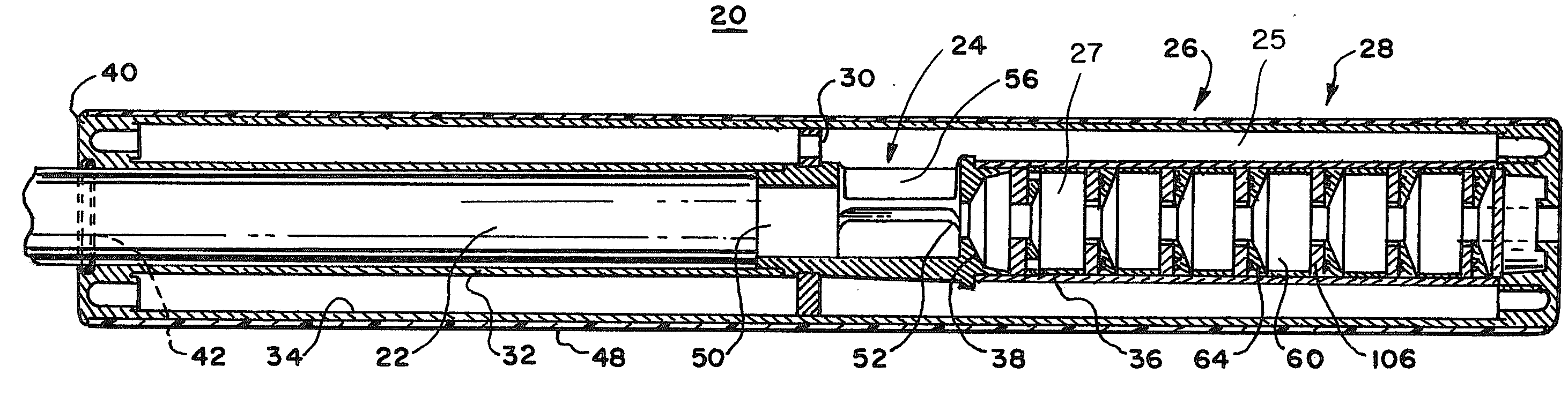
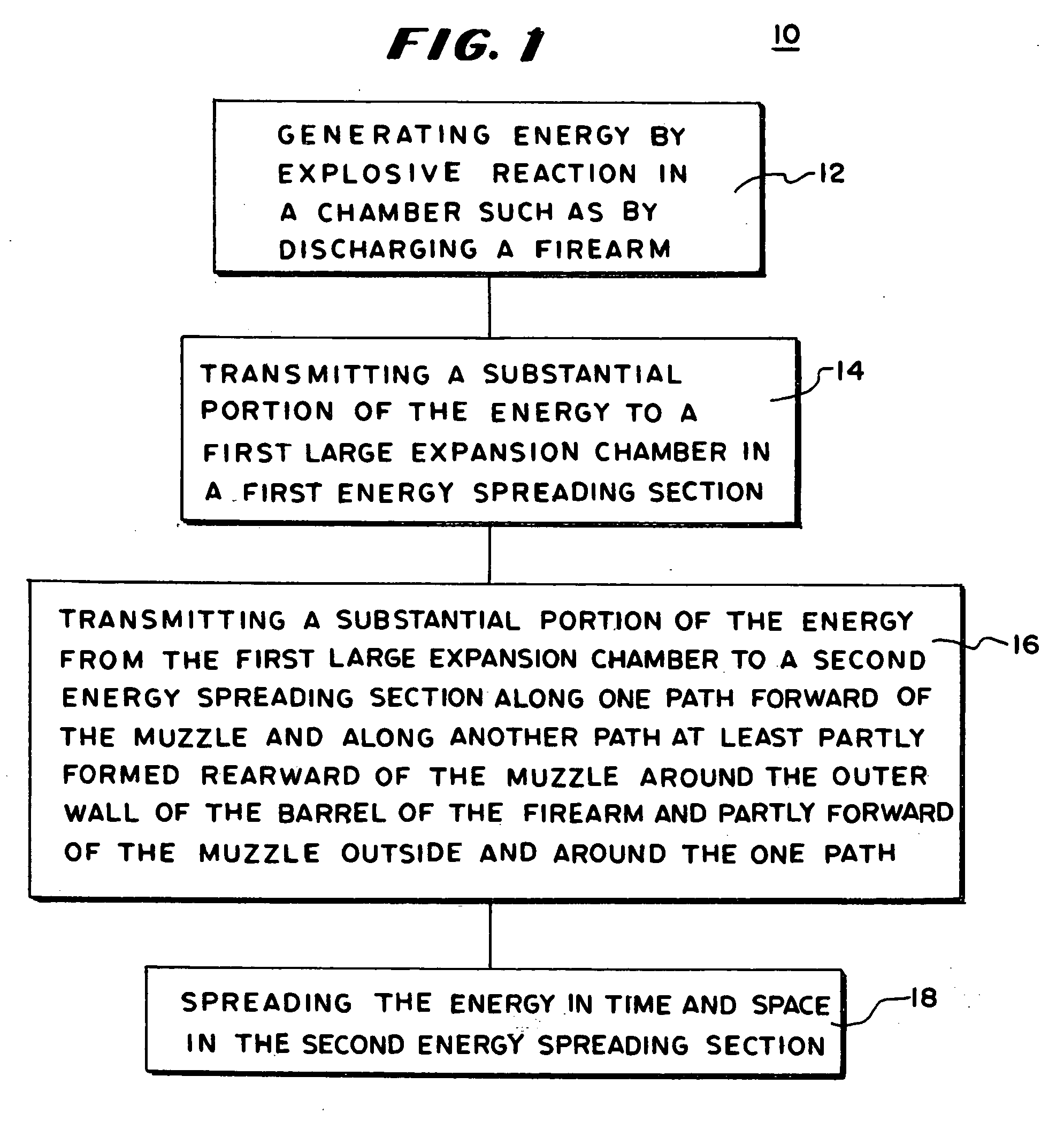
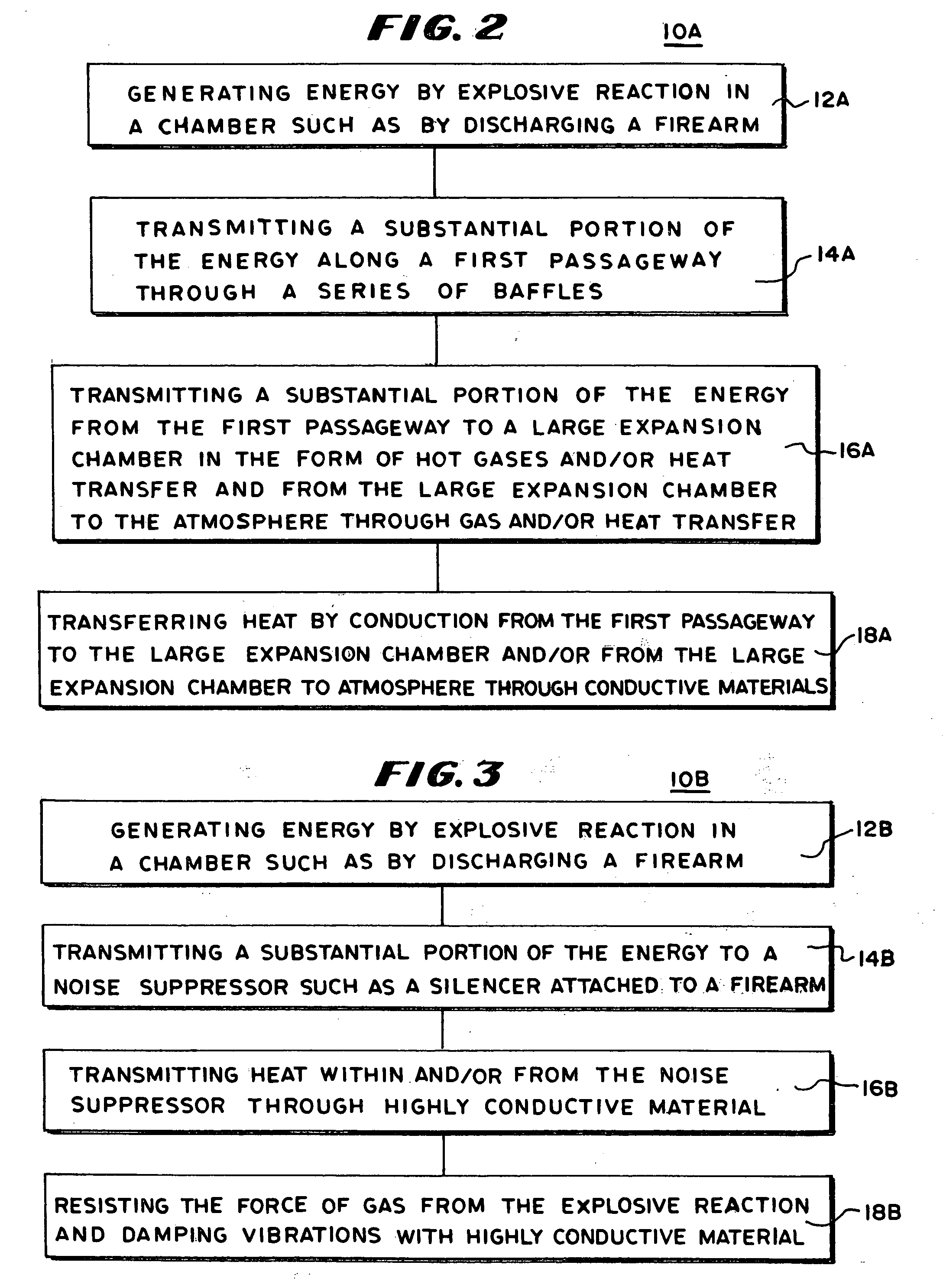
[0040]In FIG. 1, there is shown a flow diagram of a process 10 of firing a firearm utilizing a silencer in accordance with an embodiment of the invention including the step 12 of generating energy by explosive reaction in a chamber such as by discharging a firearm; the step 14 of transmitting a substantial portion of the energy to a first large expansion chamber which functions as a first energy spreading section, the step 16 of transmitting a substantial portion of the energy from the first large expansion chamber to a second energy spreading section; and the step 18 of the first large expansion chamber rapidly spreading the energy in time and space within the central longitudinal axis of the silencer to reduce the temperature and pressure of the gas from discharge before it contacts the baffles or other solid members than can be degraded excessively by the heat and pressure.

[0041]In this specification, the term “energy spreading” means increasing the area over which energy is acti...


PUM


Abstract

A suppressor for a firearm includes a first gas expansion section of relatively large size sufficient to reduce the temperature and pressure of the gas expelled from a muzzle during discharge of the firearm to a level that avoids rapid degrading of structural members such as baffles in the suppressor that are downstream of the muzzle. The gas is channeled through multiple paths to distribute its energy more equally. Preferably, the suppressor is formed with a lightweight, thermally-conductive composite portion. The composite portion provides lightweight, bursting strength with good thermal conductivity and little contribution to vibrational instability of the muzzle to which it is attached. The composite portion may be of a carbon fiber, silicon, boron, or metallic base. In one embodiment, a first expansion chamber is in communication with the muzzle and with a second expansion chamber and in another embodiment, the first expansion chamber communicates with the muzzle and with the second expansion chamber The composite portions of the suppressor provide good bursting strength and heat conductivity with light weight. In some embodiments, a series of baffles creates turbulence in the gas, slowing its motion and distributing the energy more evenly over space.

Description

BACKGROUND OF THE INVENTION[0001]This invention relates to energy suppressors such as silencers including energy suppressors using composite structures.[0002]It is known to reduce the report of firearms by leveling the energy from firing over time and space. This is done by channeling the gas formed by firing the firearm through a series of compartments and / or pathways. The gas is expanded in the chambers and pathways in a manner that slows its motion in any one direction and its energy absorbed by solid objects with a slower response time such as baffles along some of the pathways. Moreover, energy that is in the form of heat is dissipated in space with minimum of rapid thermal expansion of gas that would otherwise increase the velocity of the gas in a single direction. In this manner, the energy from the explosion is spread in time and space to reduce the intensity of sound caused by the sudden forced motion of air propelled by the energy.[0003]In one prior art sound suppresser or...

Claims


Application Information

Patent Timeline
Patent Type & Authority Applications(United States)
IPC IPC(8): F41A21/30
CPCF41A21/30
Inventor PETERSEN, BYRON S.
Owner PETERSEN BYRON S
Why Eureka
Try Eureka