Seating control device for a valve for a split-cycle engine

a control device and split-cycle engine technology, applied in the direction of machines/engines, mechanical apparatus, non-mechanical valves, etc., can solve the problems of unavoidable variations in parameters, limited flexibility, and high cost of cam-driven actuation mechanisms

Inactive Publication Date: 2010-07-22
SKADERI GRUP LLC
View PDF10 Cites 10 Cited by
  • Summary
  • Abstract
  • Description
  • Claims
  • Application Information

AI Technical Summary

Benefits of technology

[0039]In one embodiment, a spacer is provided between the upper snubber element and the lower snubber element to limit the minimum separation between the upper snubber element and the lower snubber element.
[0044]In one embodiment, a spacer is provided between the lower snubber element and the closed end of the vessel, to limit the minimum separation between the lower snubber element and the closed end of the vessel.
[0052]In one embodiment, flow of fluid from the vessel through either or both the lower and upper ports is prevented.

Problems solved by technology

A cam driven actuation mechanism is efficient and fast, but has limited flexibility.
For split-cycle engines which ignite their charge after the expansion piston reaches its top dead center position (such as in the Scuderi and Branyon patents), the dynamic actuation of the crossover valves is very demanding.
Problematically, the heights of the ramps of crossover valves 24 and 26 are so restricted that unavoidable variations in parameters that control ramp height and that are normally less significant in their effect on the larger lift profiles of conventional engines, now become critical.
However, prior art HLAs are normally one of the main contributing factors in reducing valve train stiffness which, in turn, limits the maximum engine operating speed at which the valve train can safely operate and the acceleration that the valve train can achieve.
Therefore, a prior art HLA cannot be used with the split cycle engine 10 in the conventional configuration, because the valves of a split cycle engine 10 need to actuate much more rapidly than those in a conventional engine.
Consequently, the seating velocity is too high for safe operation and, as a result, the crossover valve would crash against its seat.

Method used


Image

  • Seating control device for a valve for a split-cycle engine
  • Seating control device for a valve for a split-cycle engine
  • Seating control device for a valve for a split-cycle engine

Examples


first embodiment

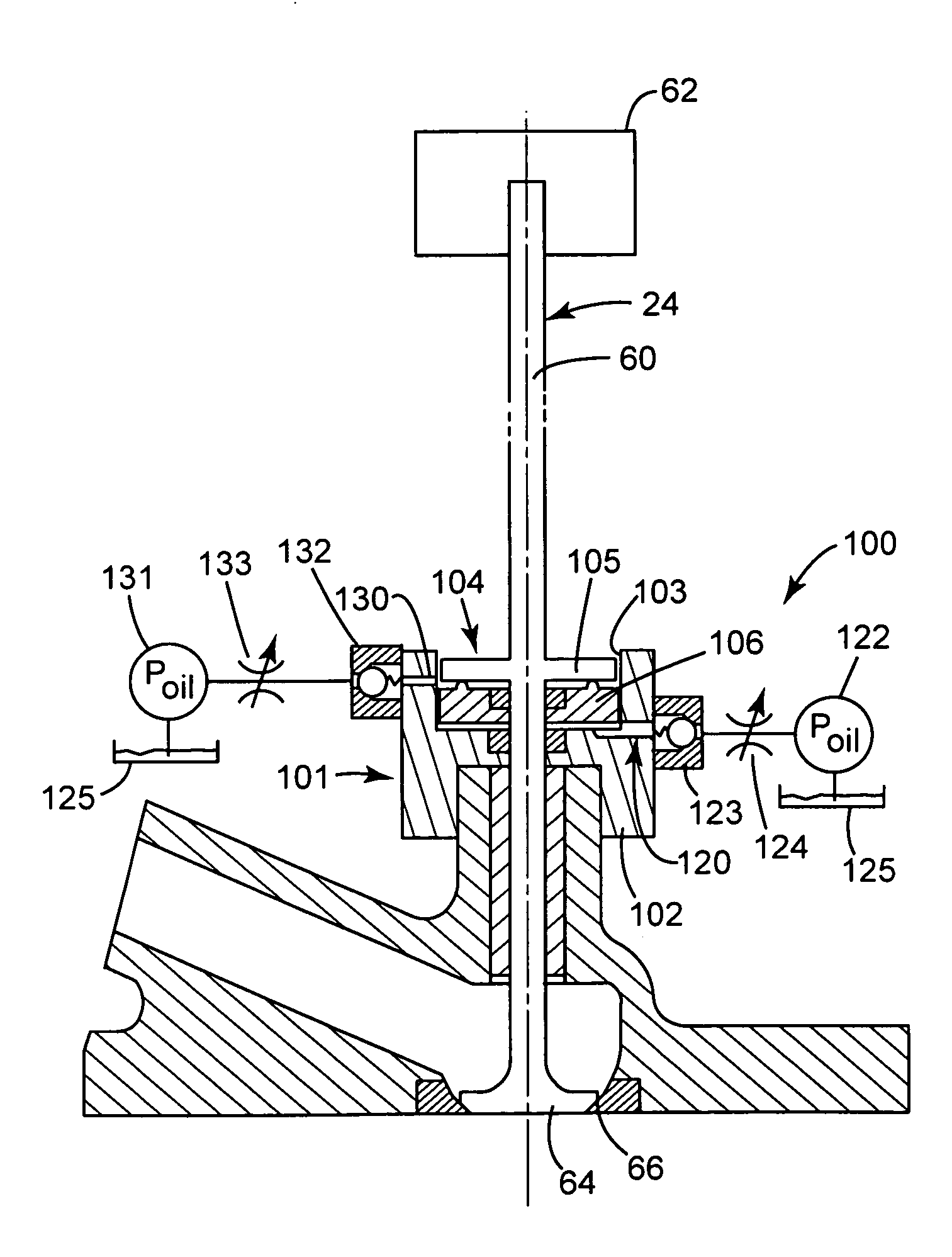
[0081]FIGS. 4, 5A and 5B show a seating control device 100 according to the present invention. In FIG. 4, the device 100 is shown connected, in line, with the valve stem 60 of the XovrC valve 24. In other embodiments, the device may be associated with the valve stem 60 by other means, for example a mechanical (lever, gearing etc) or hydraulic connection. Additionally, the seating control device 100 may be associated with the XovrE valve 26 (not shown).

[0082]The valve 24 is operated using a camless actuation system 62, shown schematically. The camless actuation system 62 may have one or more combinations of mechanical, hydraulic, pneumatic, and / or electrical components or the like.

[0083]With reference to FIGS. 5A and 5B, the seating control device 100 comprises a housing 101 having a base 102. The housing 101 has a central bore 103 defining a vessel 104, the vessel 104 containing a fluid. The fluid may be oil, or any other substantially incompressible fluid.

[0084]An upper snubber ele...

embodiment 100

[0100]In order to make the lower snubber element translatable, the position of the lower snubber element 106 with respect to the vessel 104 is hydraulically controlled, by altering the amount of fluid in the lower volume 160. Consequently in this embodiment 100, and as will be discussed in greater detail herein, the previously discussed Parameter A for controlling the squish effect, i.e., the distance between the upper 105 and lower 106 snubber elements at the point valve 24 closes is adjustable (i.e. it may no longer be a fixed distance).

[0101]A lower port 120 is provided in fluid communication with the lower volume 160. At least a part 121 of the lower port 120 is recessed in the bottom surface 113 of the bore 103. The recessed part 121 ensures that fluid passing through the lower port 120 may exert a force on at least a part of the lower surface 112 of the lower snubber element 106 even if the lower snubber element 106 abuts the bottom surface 113 of the bore 103.

[0102]A lower su...

second embodiment

[0134]In this second embodiment, the position of the lower snubber element 206 is controlled by a lever 270, pivotable at a first end 271, to control the position of the lower snubber element 206 with respect to the vessel 204. A second end 272 of lever 270 is associated with a hydraulic lash adjuster 280, the function of which will be described in more detail below.

[0135]A bearing element 276 is provided between the lever 270 and an arcuate lower surface 212 of the lower snubber element 206. The bearing element 276 has a substantially arcuate upper surface 277, which engages with the corresponding arcuate surface 212 of the lower snubber element 206. The bearing element 276 and lever 270 are provided with bores 278, 279 to receive the stem 60 of valve 24 therein. The bores 278, 279 are sized such that they do not contact the stem 60 at any point of rotation of the lever 270.

[0136]As the lever 270 rotates about its first end 271 (the pivot) in an anticlockwise direction, the lever 2...


PUM


Abstract

A seating control device for a valve, comprising:a vessel for containing a fluid;an upper snubber element translatably receivable in the vessel for controlling the seating velocity of a valve associated therewith; anda lower snubber element translatably receivable in the vessel, adjacent the upper snubber element, presenting a surface to the upper snubber element, for controlling the seating of the valve.

Description

TECHNICAL FIELD[0001]The present invention relates to a seating control device for a valve. More specifically, the present invention relates to a seating control device for a valve of camless split-cycle engines.BACKGROUND OF THE INVENTION[0002]For purposes of clarity, the term “conventional engine” as used in the present application refers to an internal combustion engine wherein all four strokes of the well known Otto or diesel cycle (the intake, compression, expansion and exhaust strokes) are contained in each piston / cylinder combination of the engine. Each stroke requires one half revolution of the crankshaft (180 degrees crank angle (CA)), and two full revolutions of the crankshaft (720 degrees CA) are required to complete the entire Otto cycle in each cylinder of a conventional engine.[0003]Also, for purposes of clarity, the following definition is offered for the term “split-cycle engine” as may be applied to engines disclosed in the prior art and as referred to in the presen...

Claims


Application Information

Patent Timeline
Patent Type & Authority Applications(United States)
IPC IPC(8): F02B33/22F16K25/00F01L9/10F01L9/16F01L9/20
CPCF01L1/16F01L9/02F01L9/026F02B33/22F01L2003/258F01L2009/0451F01L9/04F01L9/16F01L2009/2151F01L9/10F01L9/20
Inventor MELDOLESI, RICCARDOSCUDERI, STEPHEN PETER
Owner SKADERI GRUP LLC
Why Eureka
Try Eureka