Increasing Thermal Conductivity of Host Polymer Used With Laser Engraving Methods and Compositions

a technology of host polymer and thermal conductivity, which is applied in the direction of microwave heating, paper/cardboard containers, and confirming the correctness of markings, etc., can solve the problems of visible discoloration in thermoplastics, insufficient contrast of laser markings of some types of materials, and limitations still exist, so as to improve grayscale engraving and increase thermal conductivity of host materials , the effect of improving the thermal conductivity

Inactive Publication Date: 2010-07-22
L 1 SECURE CREDENTIALING
View PDF1 Cites 14 Cited by
  • Summary
  • Abstract
  • Description
  • Claims
  • Application Information

AI Technical Summary

Benefits of technology

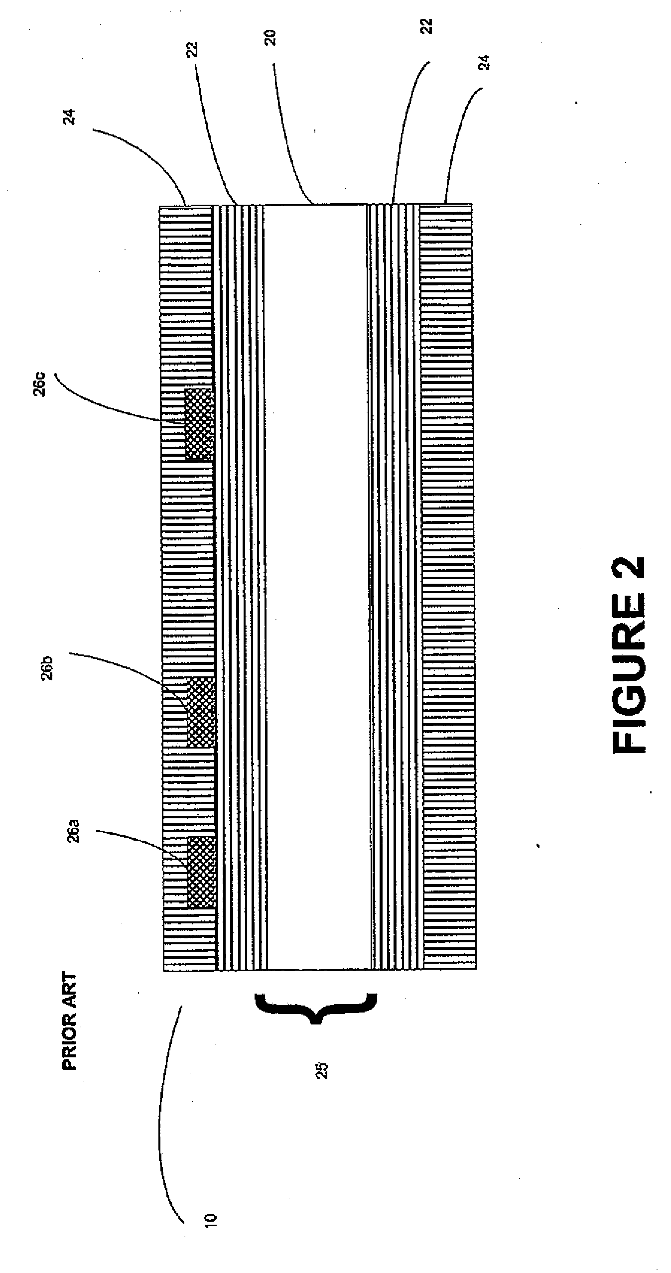
[0017]Centrally issued identification documents can be produced from digitally stored information and generally comprise an opaque core material (also referred to as “substrate”), such as paper or plastic, sandwiched between two layers of clear plastic laminate, such as polyester, to protect the aforementioned items of information from wear, exposure to the elements and tampering. The materials used in such CI identification documents can offer the ultimate in durability. In addition, centrally issued digital identification documents generally offer a higher level of security than OTC identification documents because they offer the ability to pre-print the core of the central issue document with security features such as “micro-printing”, ultra-violet security features, security indicia and other features currently unique to centrally issued identification documents. Another security advantage with centrally issued documents is that the security features and / or secured materials used to make those features are centrally located, reducing the chances of loss or theft (as compared to having secured materials dispersed over a wide number of “on the spot” locations).
[0061]Although some companies offer laser engraving document materials, such materials and / or the amount of equipment required to laser engrave such materials (especially for high quality grayscale images on identification documents) can be prohibitively expensive. At least some embodiments of our invention can overcome at least some of these and other limitations of the prior art. At least some embodiments of our invention offer a less expensive option for laser engraving with improved grayscale engraving, and ease of manufacture, without giving up desired security features.

Problems solved by technology

The area irradiated by the laser absorbs the laser energy and produces heat which causes a visible discoloration in the thermoplastic.
Despite the advantages of laser engraving, certain limitations still exist.
Even when using known laser-enhancing additives, laser marking of some types of materials does not produce an adequate contrast for all applications.
Some types of materials, such as silica filled polyolefin, TESLIN core ID documents and TESLIN composite structures (TESLIN is available from PPG Industries, Inc., Pittsburgh, Pa.) using conventional over-laminate materials, are not easily laser engraved.
Further, even with use of known laser additives, laser engraving can take too much time and / or too much laser energy to be useful in some manufacturing environments.
Another limitation of laser engraving has been marking speeds.
Laser engraving machines are quite costly at present, and despite various improvements made to laser engraving machines to increase speed, laser engraving documents at an acceptable speed and throughput and image quality continues to require, in many instances, multiple laser engraving machines.
Although some companies offer laser engraving document materials, such materials and / or the amount of equipment required to laser engrave such materials (especially for high quality grayscale images on identification documents) can be prohibitively expensive.

Method used


Image

  • Increasing Thermal Conductivity of Host Polymer Used With Laser Engraving Methods and Compositions
  • Increasing Thermal Conductivity of Host Polymer Used With Laser Engraving Methods and Compositions
  • Increasing Thermal Conductivity of Host Polymer Used With Laser Engraving Methods and Compositions

Examples


second embodiment

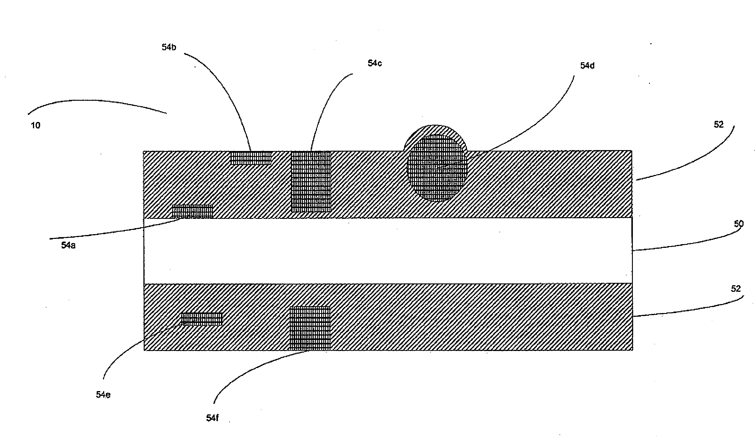
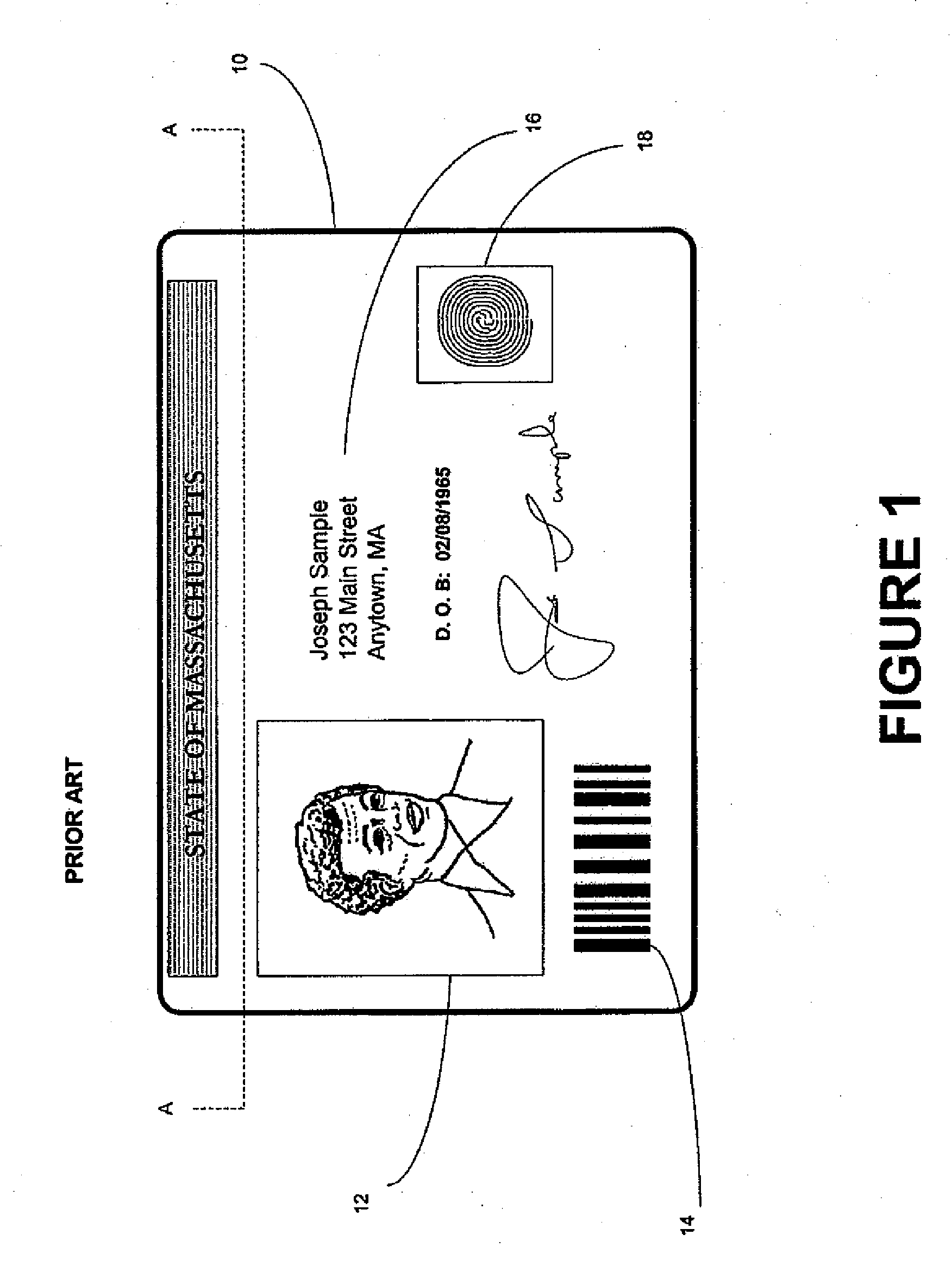
[0156]For example, FIG. 4 is an illustrative cross sectional view of an identification document in accordance with the first aspect of the invention. In the embodiment of FIG. 4, the ID document 10 preferably includes a multi-layered structure. For purposes of illustration, however, the ID document 10 may have a front outward appearance generally similar to the identification document 10 of FIG. 1, although the construction and components of the cross-section shown in FIG. 4 differs from the prior art. In the embodiment of FIG. 4, the portion of first laminate 52 containing the inventive laser enhancing additive is disposed at least partially within a layer of another material, such as so-called “plain” laminate 56 (i.e., laminate that does not contain the inventive laser enhancing additive). When a laser beam is applied to the first laminate 52, a third indicium 54G is formed. The plain laminate 56 may comprise a material that is inherently sensitive to laser radiation or can be a ...

third embodiment

[0157]FIG. 5 is an illustrative cross sectional view of an identification document 10 in accordance with the first aspect invention. In the embodiment of FIG. 5, the ID document 10 preferably includes a multi-layered structure. For purposes of illustration, however, the ID document 10 may have a front outward appearance generally similar to the identification document 10 of FIG. 1, although the construction and components of the cross-section shown in FIG. 5 differs from the prior art. In the embodiment of FIG. 5, a first portion of the inventive laser enhancing additive is disposed in a first laminate layer 52 and a second portion of the inventive laser enhancing additive is disposed in a second laminate layer 55. Specifically, in this embodiment, the first laminate layer 52 contains an effective amount of at least one of copper potassium iodide (CuKI3), copper iodide (CuI), Potassium Iodide (KI), Sodium Iodide (NaI), and Aluminum Iodide (AlI) and the second laminate layer 55 conta...

fourth embodiment

[0164]The inventive laser enhancing additive also can be used in a laminate that has one or more additional laminate layers bonded over it. For example, FIG. 6 is an illustrative cross sectional view of an identification document in accordance with the invention. In the embodiment of FIG. 6, the ID document 10 preferably includes a multi-layered structure. For purposes of illustration, however, the ID document 10 may have a front outward appearance generally similar to the identification document 10 of FIG. 1, although the construction and components of the cross-section shown in FIG. 6 differs from the prior art. In FIG. 6, the ID card 10 includes a core material 50 (shown for illustrative purposes only to be about 10 mils thick) to which is laminated a layer (shown for illustrative purposes only to be about 5 mils thick) of first laminate 52 to which the inventive laser enhancing additive is added. Over the first laminate 52 is a layer of second laminate 58 (shown for illustrative...


PUM

PropertyMeasurementUnit
thickaaaaaaaaaa
thickaaaaaaaaaa
thicknessaaaaaaaaaa

Abstract

the invention provides a composition having laser engraving properties, comprising a host material and a laser enhancing additive. The host material comprises a material, such as a polymer, modified by a first process, whereby the host material as modified by the first process has increased thermal conductivity as compared to the host material before the first process. The laser enhancing additive comprises a first quantity of at least one of copper potassium iodide (CuKI3), Copper Iodide (CuI), potassium iodide (KI), sodium iodide (NaI), and aluminum iodide (AlI), and a second quantity of at least one substance selected from the group consisting of zinc sulfide (ZnS), barium sulfide (BaS), alkyl sulfonate, and thioester.

Description

CROSS REFERENCE TO RELATED APPLICATION[0001]The present application is a continuation of Ser. No. 10 / 677,092, filed Sep. 30, 2003, which is a continuation-in-part of Ser. No. 10 / 326,886, filed Dec. 20, 2002 and claims priority to 60 / 471,429, filed May 16, 2003 and claims priority to 60 / 500,204, filed Sep. 3, 2003, and claims priority to 60 / 504,352, filed Sep. 19, 2003, the contents of which are incorporated hereby by reference in their entirety:RELATED APPLICATION DATA[0002]The present application is related to U.S. patent application Ser. No. 09 / 747,735, filed Dec. 22, 2000, 09 / 602,313, filed Jun. 23, 2000, and 10 / 094,593, filed Mar. 6, 2002, U.S. Provisional Patent Application No. 60 / 358,321, filed Feb. 19, 2002, as well as U.S. Pat. No. 6,066,594. Each of the above U.S. Patent documents is herein incorporated by reference. The present application also is related to the following U.S. patent application documents:[0003]Systems, Compositions, and Methods for Full Color Laser Engrav...

Claims


Application Information

Patent Timeline
Patent Type & Authority Applications(United States)
IPC IPC(8): B42D15/00B29C65/02B29C65/16B23K26/42B41M5/24C08F2/46C08J3/28G03C1/00G03C1/492G03C1/494G03C1/76G06K5/00H01S
CPCB23K26/421B29C65/1616Y10S430/146B41M5/24Y10T156/10B41M3/16B23K26/60Y10T428/31504Y10T428/31507
Inventor LABREC, BRIAN
Owner L 1 SECURE CREDENTIALING
Why Eureka
Try Eureka