Electrolyte for electrochemical device and the electrochemical device thereof

Active Publication Date: 2010-07-22
TAIWAN HOPAX CHEM MFG
0 Cites 2 Cited by

AI-Extracted Technical Summary

Problems solved by technology

Therefore, people invest a lot of time in researches of lithium ion batteries.
However, one of the drawbacks of lithium ion batteries is the capacity fading during repeated charging-discharging cycles.
The more the capacity of a lithium ion battery has, the more serious this problem is.
It will result in poor charging-discharging performances of battery under low temperature.
), but it is prone to produce co...

Benefits of technology

[0023]From above, a new additive is used in the electrolyte of present invention for an electrochemical. The new additive can form a special SEI layer on the surface of the carbonaceous material of the anode to suppress the occurrence of exfoliation, thereby enhancing the lifetime of batt...

Abstract

The present invention provides an electrolyte containing novel additive for electrochemical device and the electrochemical device thereof. The additive is a compound represented by below formula (I):
wherein R1 and R2 are independently hydrogen, methyl, ethyl, or halogen; n and m are independently 1, 2, or 3. The additive of the present invention can protect the surface of the carbonaceous material on the anode and suppress the occurrence of exfoliation, thereby increasing the lifetime of the electrochemical device. Furthermore, the additive of the present invention also slows down the decay of capacity on the cathode during charging-discharging cycles, and hence maintains a better performance.

Application Domain

Electrolytic capacitorsOrganic electrolyte cells +3

Technology Topic

HalogenElectrochemical cell +4

Image

  • Electrolyte for electrochemical device and the electrochemical device thereof
  • Electrolyte for electrochemical device and the electrochemical device thereof
  • Electrolyte for electrochemical device and the electrochemical device thereof

Examples

  • Experimental program(5)

Example

Example 1
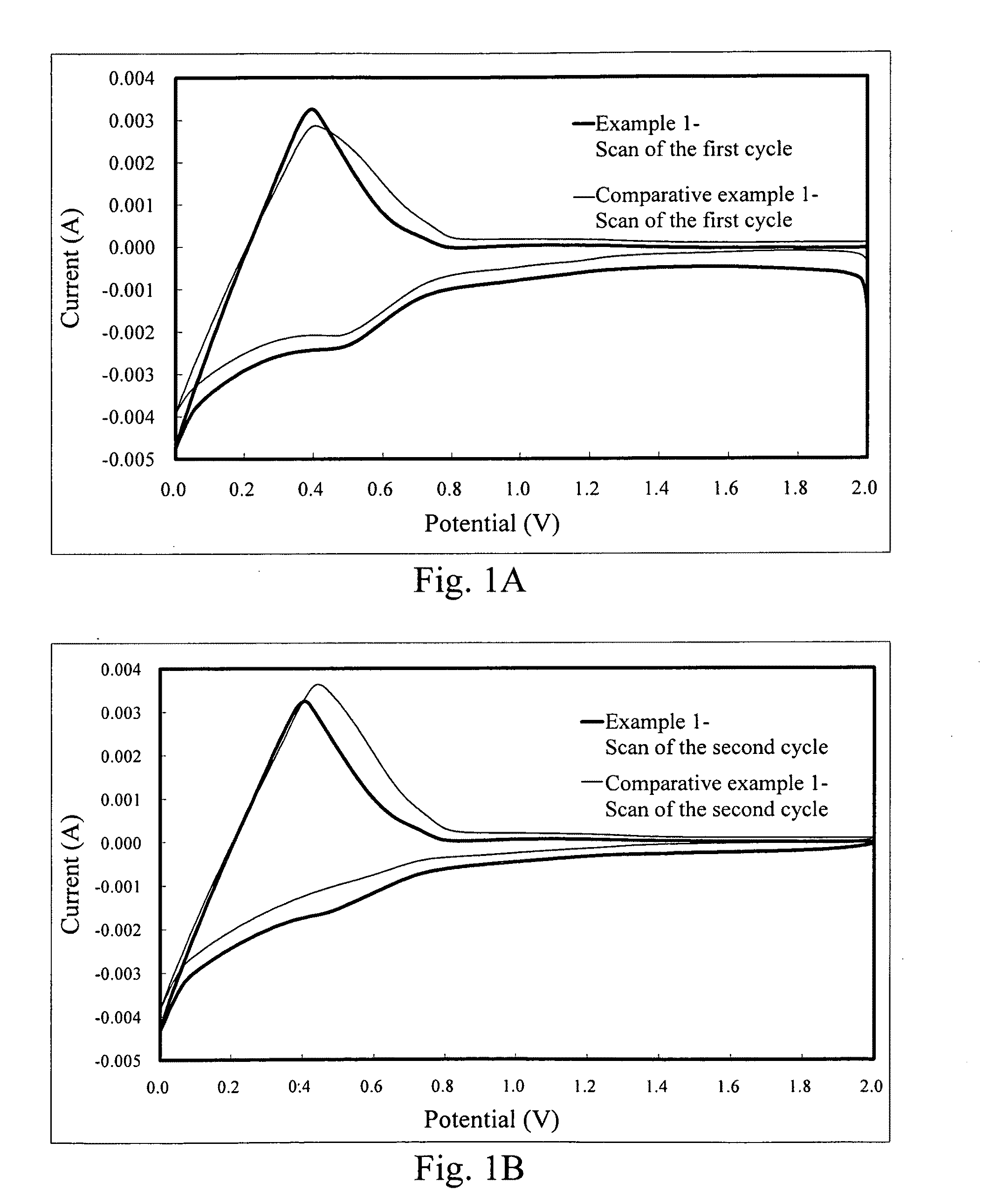
Cyclic Voltammetry Test of the Lithium Ion Secondary Battery with the Additive of the Present Invention
[0038]The test according to the example 1 of the present invention was conducted in the lithium ion secondary battery. Table 1 listed the materials and components used in the lithium ion secondary batteries of the example 1. The comparative example 1 used the same materials as the example 1 except no additive. The electrode materials used in the present invention and the methods for producing the same were known in the art and the technical features of the present invention can be easily understood and performed by those skilled in the art according to the disclosure herein, so the processes were not mentioned in detail here. Besides, the concentration of the additive used in Table 1 was 1 wt %; however, the concentration of the additive can be in the range of 0.1 wt % to 10 wt %, which was easily understood by those skilled in the art. Therefore, the concentration recited in Table 1 was used for illustration, not used for limit the present invention.
TABLE 1 the materials and components used in the lithium ion secondary batteries of the example 1 Anode sheet NG/conductive carbon black/PVdF = 90/3/7 (wt %) Electrolyte 1 Organic EC:DEC = 1:1 (by weight) solvent Salt 1M LiPF6 Additive *NG: natural crystalline flake graphite PVdF: polyvinylidene difluoride DEC: diethyl carbonate EC: ethylene carbonate
Cyclic Voltammetry Test

Example

[0039]The batteries of the example 1 and the comparative example 1 were conducted cyclic voltammetry (CV) tests. As above-mentioned, the materials of the electrode sheet used in the CV test and the method for producing the same were known in the art, which were not used for limit the present invention. A preparation of an electrode sheet used in the CV test included, but was not limited to, cutting a rolled anode sheet into a size of 2×4 cm2, wherein the slurry-coated part (i.e. the part of anode sheet used in Table 1) was 2×2 cm2, and the part of copper foil was 2×4 cm2; welding a Ni handle to the center of the part of the copper foil on the cut electrode sheet by ultrasonic welding machine; and sticking insulating tape to the face of the welded anode sheet and the edge thereof to leave an circular area having diameter of 13 mm for test.
[0040]CV test was conducted in an electrolytic bath with an electrolyte containing EC/DEC (weight ratio of 1/1) and 1M LiPF6. Moreover, the cut and stuck anode sheet was connected to a working electrode, and lithium metal was used as a counter electrode and reference electrode. The test was carried out in a glove box under argon atmosphere at room temperature, wherein the concentration of H2O and O2 was less than 10 ppm. The condition for test was scanning speed of 1.0 mV/s and scanning voltage of 0˜2 V. The result of test was shown in FIG. 1B. During scan of the second cycle, an apparent peak was observed within 0.4˜0.6 V when the additive of the present invention was added, indicating that the SEI layer on the anode was continuously formed. From above results, the additive of the present invention was benefic to promote the formation of steady SEI layer on the anode.
[0041]After cyclic voltammetry test, the surface of anode sheet was observed using surface electron microscopy. The result was shown in FIG. 2. As shown in FIG. 2, a thick SEI layer was formed on the surface of the carbonaceous material in the example 1. Compared to the SEI layer of the example 1, that of the comparative example 1 was thin and had loose structure. This proved that the additive used in the example was useful for forming a steady SEI layer.

Example

Example 2
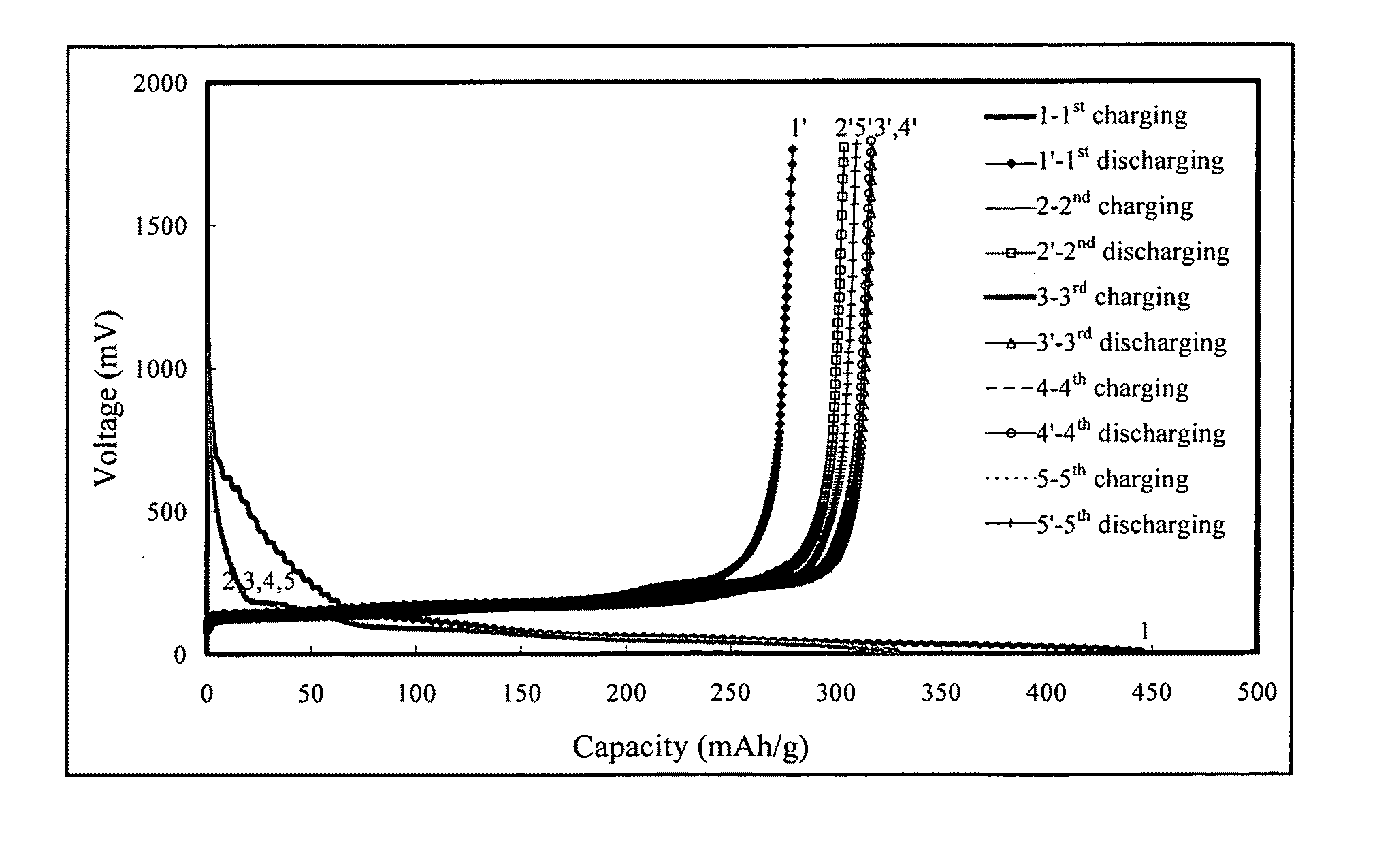
Charging-Discharging Test of the Lithium Ion Secondary Battery with the Additive of the Present Invention
[0042]The test according to the example 2 of the present invention was conducted in the lithium ion secondary battery. Table 2 listed the materials and components used in the lithium ion secondary batteries of the example 2. The comparative example 2 used the same materials as the example 2 except for no additive, the comparative example 3 used the same materials as the example 2 except for use of 1.0 wt % PS as an additive, and the comparative example 4 used the same materials as the example 2 except for use of 1.0 wt % VC as an additive.
TABLE 2 the materials and components used in the lithium ion secondary batteries of the example 2 Anode sheet NG/conductive carbon black/PVdF = 90/3/7 (wt %) Electrolyte 2 Organic PC:DEC = l:2 (by weight) solvent Salt 1M LiPF6 Additive
Charging-Discharging Test
[0043]In order to test charging-discharging performance of batteries, the batteries of the example 2 and the comparative examples 2, 3 and 4 were fabricated into coin half-cell, and then connected with a charging-discharging tester (8 channels). During the charging-discharging test, the batteries were charged at 0.1 C to a cut-off voltage of 0.003 V, and then discharged at 0.1 C to a cut-off voltage of 1.8 V, which was defined as a charging-discharging cycle. In this test, there was totally five charging-discharging cycles. Besides, changes of voltage were recorded by a computer during the test and the resulting data were calculated to obtain the values of capacity.
[0044]FIG. 3A to FIG. 3D showed the results of charging-discharging tests according to the batteries of the comparative examples 2, 3, and 4, and the example 2, respectively. In these figures, FIG. 3A showed that the battery of the comparative example 2 containing no additive can not normally discharge during the first discharging cycle, indicating that the carbonaceous materials collapsed during the first cycle charging-discharging test. FIG. 3B showed that the battery of the comparative example containing 1 wt % PS can normally discharge during the first cycle charging-discharging test; however, the charging and discharging capacity decayed quickly after the second cycle charging-discharging test. The result demonstrated that the carbonaceous material collapsed after the second cycle charging-discharging test. Besides, FIG. 3B also showed that the fifth reversible discharging capacity was only 21 mAh/g, lower than 7% of the first discharging capacity. According to FIG. 3C, it showed that the battery of the comparative example 4 containing 1 wt % VC collapsed during the first cycle charging-discharging test and the first reversible discharging capacity was lower than 20 mAh/g. FIG. 3D showed that the battery of the example 2 containing 1 wt % compound of formula (I-a) had a discharging capacity of more than 300 mAh/g, indicating that the battery still maintained an excellent reversible charging-discharging property after continuous five charging-discharging test. From the above results, the electrolyte of the present invention was useful for suppressing the exfoliation of materials used in the batteries, and therefore enhanced the lifetime of batteries.

PUM

no PUM

Description & Claims & Application Information

We can also present the details of the Description, Claims and Application information to help users get a comprehensive understanding of the technical details of the patent, such as background art, summary of invention, brief description of drawings, description of embodiments, and other original content. On the other hand, users can also determine the specific scope of protection of the technology through the list of claims; as well as understand the changes in the life cycle of the technology with the presentation of the patent timeline. Login to view more.

Similar technology patents

Numerical control machine

ActiveUS20130226355A1suppress occurrencereduction of finish quality
Owner:OKUMA CORP

Image forming apparatus

InactiveUS20180234563A1suppress occurrence
Owner:SHARP KK

Classification and recommendation of technical efficacy words

  • suppress occurrence
  • suppress effect

Semiconductor device

InactiveUS20120267696A1suppress effecthigh reliability
Owner:SEMICON ENERGY LAB CO LTD

Rattle-free component pairing

InactiveUS20100326223A1suppress effectlow weight
Owner:GETRAG GETRIEBE & ZAHNRADFABRIK HERMANN HAGENMEYER GMBH & CO KG

Semiconductor structure and method for manufacturing the same

ActiveUS20150145046A1enhance control capabilitysuppress effect
Owner:INST OF MICROELECTRONICS CHINESE ACAD OF SCI
Why Eureka
Try Eureka