This helps you quickly interpret patents by identifying the three key elements:
Problems solved by technology
Method used
Benefits of technology
Benefits of technology
[0006]An object of the present invention is to provide a hybrid vehicle suppressed in occurrence of vibration.
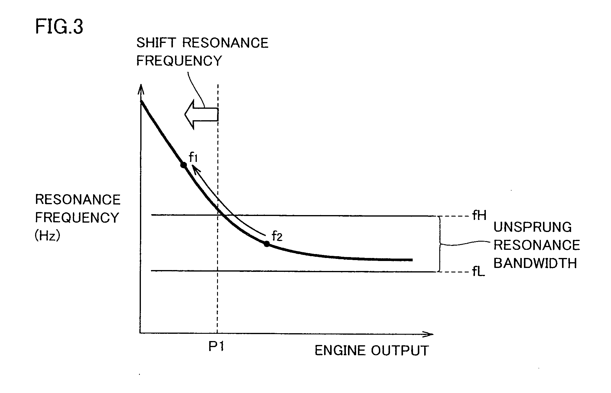
[0008]Preferably, the resonance frequency of a transmission mechanism transmitting power from the internal combustion engine to the transmission member via the power split device changes according to the output from the internal combustion engine. The control unit reduces the output from the internal combustion engine until the resonance frequency of the transmission mechanism falls outside an unsprung resonance bandwidth.
[0013]Preferably, the resonance frequency of a transmission mechanism transmitting power to the transmission member from the internal combustion engine via the power split device changes according to the output from the internal combustion engine. The control unit reduces the output from the internal combustion engine until the resonance frequency of the transmission mechanism falls outside the unsprung resonance bandwidth.
[0016]According to the present invention, vibration can be suppressed when the hybrid vehicle runs on a road where irregularities are present periodically.
Problems solved by technology
If the unsprung resonance point matches the torsional resonance point of the input shaft, excessive torque will be generated at the input shaft.
Thus, since the generated torque will be excessive and periodic in the case where the input variation towards the input shaft varies periodically and intermittently, control of the motor generator cannot keep up with the variation.
Accordingly, vibration cannot be suppressed and will become noticeable.
Method used
Image
Click on the blue label to locate the original text in one second.
Reading with bidirectional positioning of images and text.
Examples
first embodiment
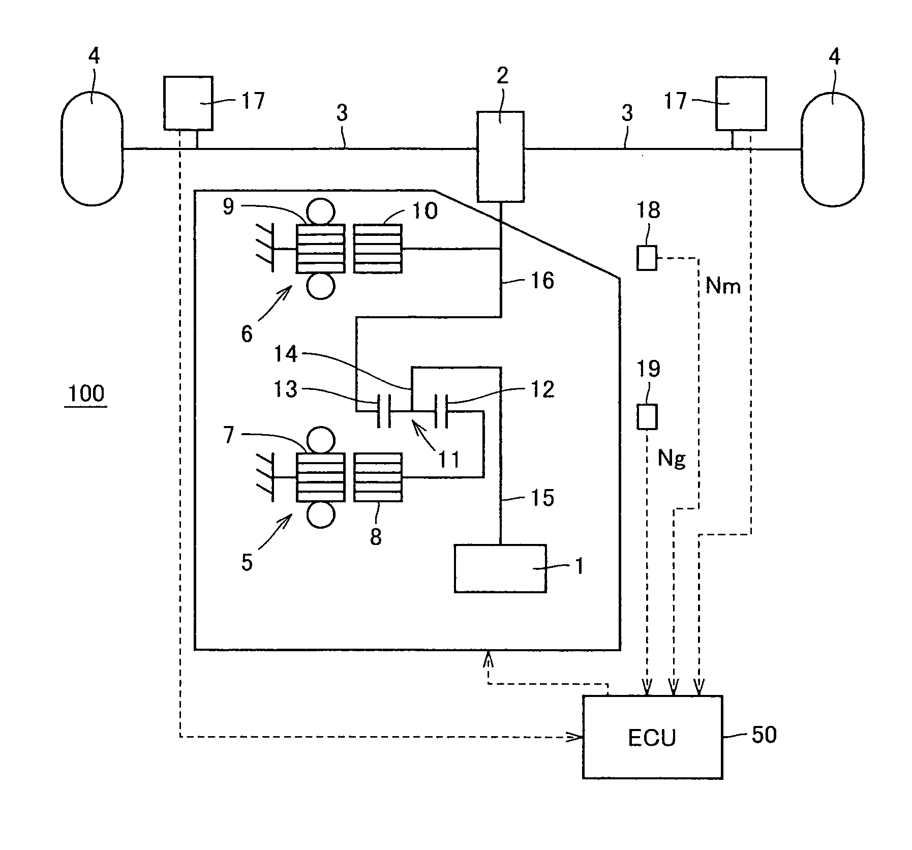
[0028]FIG. 1 is a skeleton diagram schematically representing a powertrain of a vehicle 100.
[0029]Referring to FIG. 1, vehicle 100 includes an engine 1, a first motor generator 5, a power split device 11 splitting the power from engine 1 to first motor generator 5 and a transmission member 16, a second motor generator 6, and an electronic control unit (ECU) 50.
[0031]A synchronous electric motor, for example, can be used for first motor generator 5. First motor generator 5 is configured to function as an electric motor and as a generator. A battery (not shown) is electrically ...
second embodiment
[0072]In a hybrid vehicle, connection between engine 1 and the driving device is established absent of a fluid coupling or the like. Therefore, when the rotational speed of the wheel suddenly changes such as in the case of harsh braking, parking lock engagement at the time of or moving, parking lock release in a slope stop mode, or change in the friction coefficient of the road, the rotational speed of engine 1 will not follow-up with the change, leading to change in the relative rotational speed of engine 1 to transmission member 16. Further, there is a possibility of excessive torque being added to transmission member 16 by the so-called inertia torque of the engine.
[0073]In order to prevent such excessive increase in torque, the control set forth below will be carried out.
[0074]FIG. 6 is a flowchart of vibration suppress control in a rapid deceleration mode executed in the second embodiment. The process steps in the flowchart are invoked and executed from a predetermined main rou...
third embodiment
[0093]In the first and second embodiments, irregularities of a road surface is detected to reduce the engine output by detecting change in the vehicle state that occurs after the wheel passes over the irregularities of the road. However, generation of unsprung resonance caused by road irregularities can be detected by another method. For example, the road surface can be examined by a non-contact sensor such as an ultrasonic sensor.
[0094]FIG. 10 is a diagram to describe a hybrid vehicle 200 of the third embodiment.
[0095]Hybrid vehicle 200 of FIG. 10 includes, in addition to the configuration of hybrid vehicle 100 described with reference to FIG. 1, an ultrasonic sensor 202 attached at the front side of the vehicle.
[0096]Ultrasonic sensor 202 can identify the irregularities of the road by directing an ultrasonic wave towards the region of the road surface located forward of the vehicle and detecting the reflected ultrasonic wave.
[0097]FIG. 9 is a flowchart of the vibration suppress co...
PUM
Abstract
A hybrid vehicle includes an engine that is an internal combustion engine, a motor generator that is a rotating electric machine used together with the engine for driving the vehicle, an output shaft transmitting power to a wheel, a transmission member coupled to the output shaft, a power split device splitting the output from the engine to the motor generator and transmission member, a detection device detecting irregularities on a road, and a control unit reducing, when the detected result by the detection device indicates generation of periodic torque variation at the output shaft, the output from the engine based on the detected result. Accordingly, a hybrid vehicle that does not require a torque limiter is provided.
Description
TECHNICAL FIELD[0001]The present invention relates to hybrid vehicles, particularly a hybrid vehicle generating the driving force for the wheel using an internal combustion engine and a rotating electric machine together.BACKGROUND ART[0002]As a vehicle taking into account environmental issues, attention is now focused on hybrid vehicles that use a motor and engine together for driving the wheel. Some hybrid vehicles take advantage of the differential action of the planetary gear mechanism to control the rotational speed by means of the electric motor or motor generator connected to the planetary gear mechanism to drive the internal combustion engine at the optimum operating point. Such vehicles are configured to cover the excessive or insufficient driving force and engine braking force through the electric motor or motor generator, and further carry out energy regeneration in a deceleration mode to improve the fuel efficiency of the internal combustion engine.[0003]Japanese Patent ...
Claims
Application Information
Patent Timeline
Application Date:The date an application was filed.
Publication Date:The date a patent or application was officially published.
First Publication Date:The earliest publication date of a patent with the same application number.
Issue Date:Publication date of the patent grant document.
PCT Entry Date:The Entry date of PCT National Phase.
Estimated Expiry Date:The statutory expiry date of a patent right according to the Patent Law, and it is the longest term of protection that the patent right can achieve without the termination of the patent right due to other reasons(Term extension factor has been taken into account ).
Invalid Date:Actual expiry date is based on effective date or publication date of legal transaction data of invalid patent.

