
Electrically-driven apparatus charging system and method

a charging system and electric motor technology, applied in secondary cell servicing/maintenance, instruments, transportation and packaging, etc., can solve the problems of further spreading to the general public and high cost of electric vehicles, and achieve the effect of promoting the spread of electric vehicles

Inactive Publication Date: 2010-07-22
KYUSHU ELECTRIC POWER CO INC
View PDF18 Cites 58 Cited by
  • Summary
  • Abstract
  • Description
  • Claims
  • Application Information

AI Technical Summary

Benefits of technology

The invention is an electrically-driven apparatus charging system that reduces exhaust emissions and promotes environmental awareness. The system includes a management terminal that detects the amount of charging to the power supply means and calculates the driving amount of the electrically-driven apparatus after the last charging. The management terminal also receives information about the power supply means and the chassis of the electrically-driven apparatus. The system calculates a reference amount of non-electrical exhaust emissions based on a preset amount of exhaust emissions from a non-electrically driven apparatus per unit driving amount and the driving amount calculated by the driving amount calculation means. The system also includes a reference information acquisition means for downloading reference information from a management center server and a Eco-point calculation means for calculating an Eco-point based on the amount of exhaust emissions reduction and the driving amount. The system can also include an Eco-point transmission means for transmitting the calculated Eco-point to the management center server. The invention promotes the use of electric vehicles and reduces exhaust emissions by providing an incentive to the owners of the electric vehicles.

Problems solved by technology

However, the electric vehicle itself is expensive, and there is a problem that this prevents further spread to the general public.

Method used


Image

  • Electrically-driven apparatus charging system and method
  • Electrically-driven apparatus charging system and method
  • Electrically-driven apparatus charging system and method

Examples


first embodiment

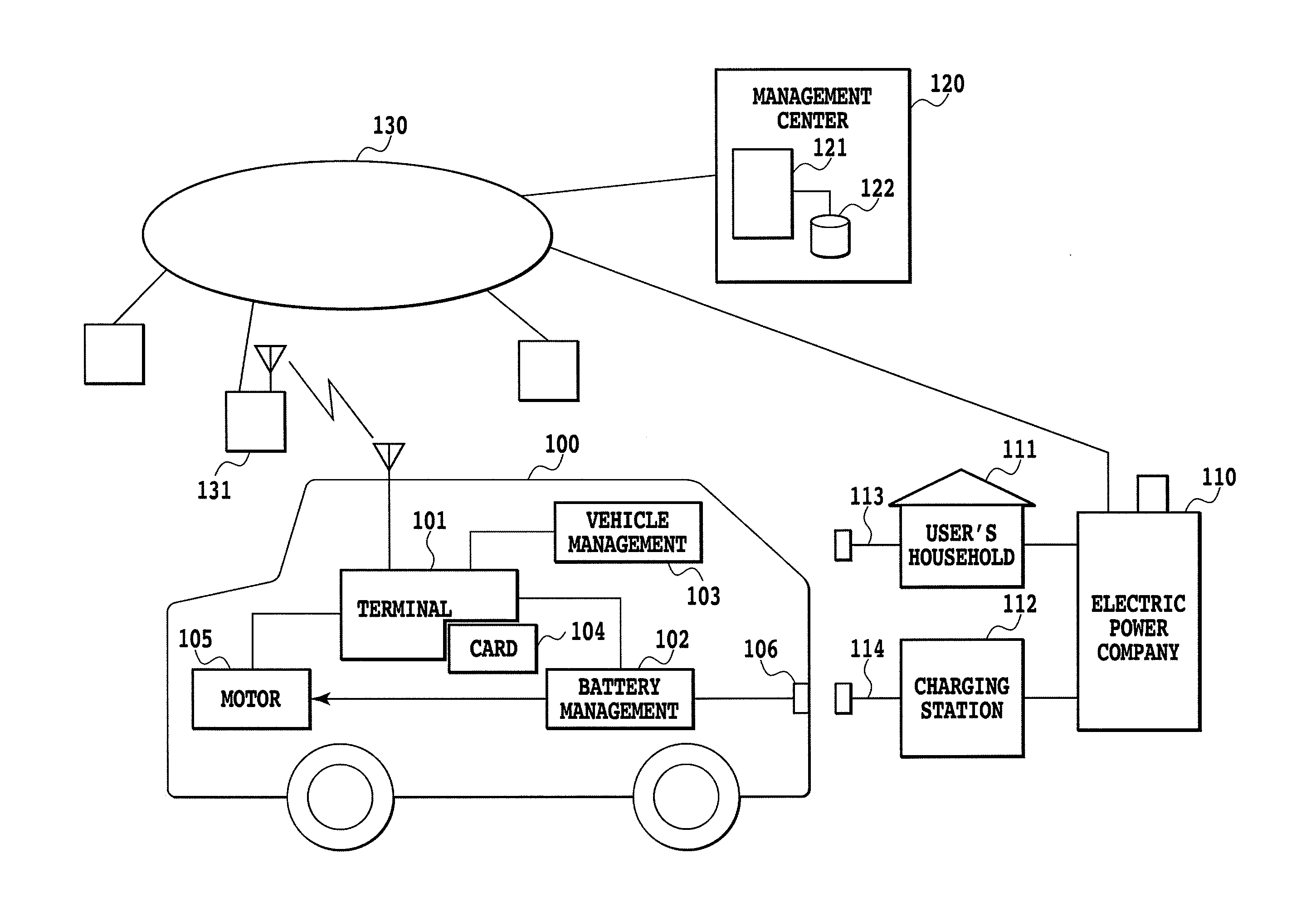
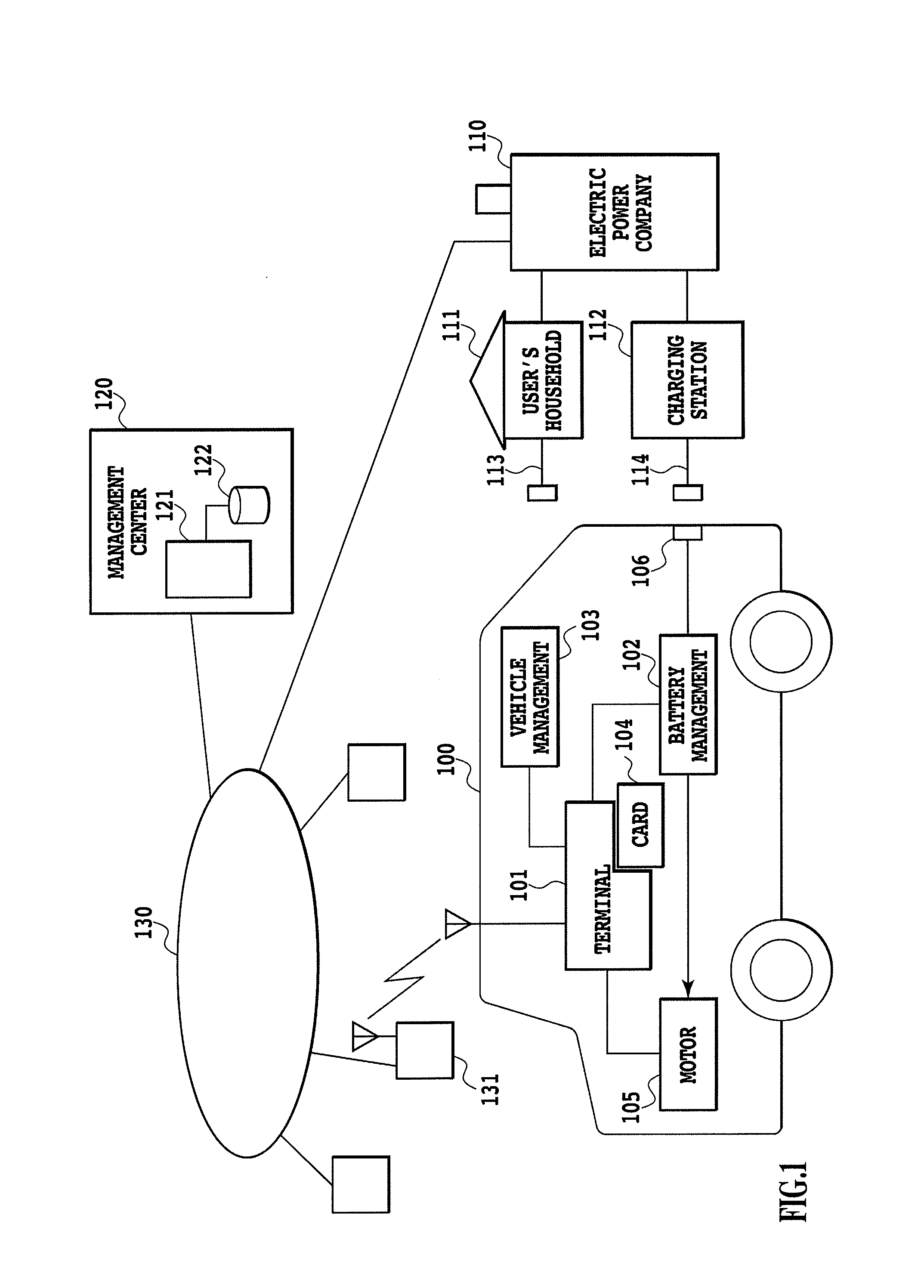
[0033]FIG. 1 is a diagram showing an outline of an electric vehicle charging system according to the present invention. As shown in FIG. 1, the electric vehicle charging system of the present invention is constituted of an electric vehicle 100, an electric power company 110, a management center 120, a network 130 that provides their connections, and the like. A battery of the electric vehicle 100 is charged with electric power provided mainly by the electric power company 110, and various kinds of charge-related information are transmitted to and received from the management center 120 or the like via the network 130 or the like. In this embodiment, the supply of the electric power is effected by the generation of the electric power mainly by a power plant of the electric power company; however, the present invention is not limited to this, and an electric power generation method or system known in the technical field may be used for the supply. Also, in this embodiment, the electri...

second embodiment

[0065]This embodiment is substantially identical in system with the above-mentioned first embodiment, but assumes a case where charging is performed from an outlet in an ordinary household, for example, after coming back home, instead of use of charging facilities in charging, such as a charging station. Therefore, processing according to this embodiment is not greatly different from that according to the first embodiment, but is different in control of a charger or a battery because the quick charger is not used.

[0066]FIGS. 5A, 5B and 5C are flowcharts showing the processing by an electric vehicle charging system using an ordinary household power supply according to this embodiment. Of the processing shown in FIGS. 5A, 5B and 5C, parts that perform the same processing as the first embodiment are indicated by the same references. Description will be given below mainly with regard to parts that are different from the first embodiment.

[0067]Before the owner authentication or the like ...

third embodiment

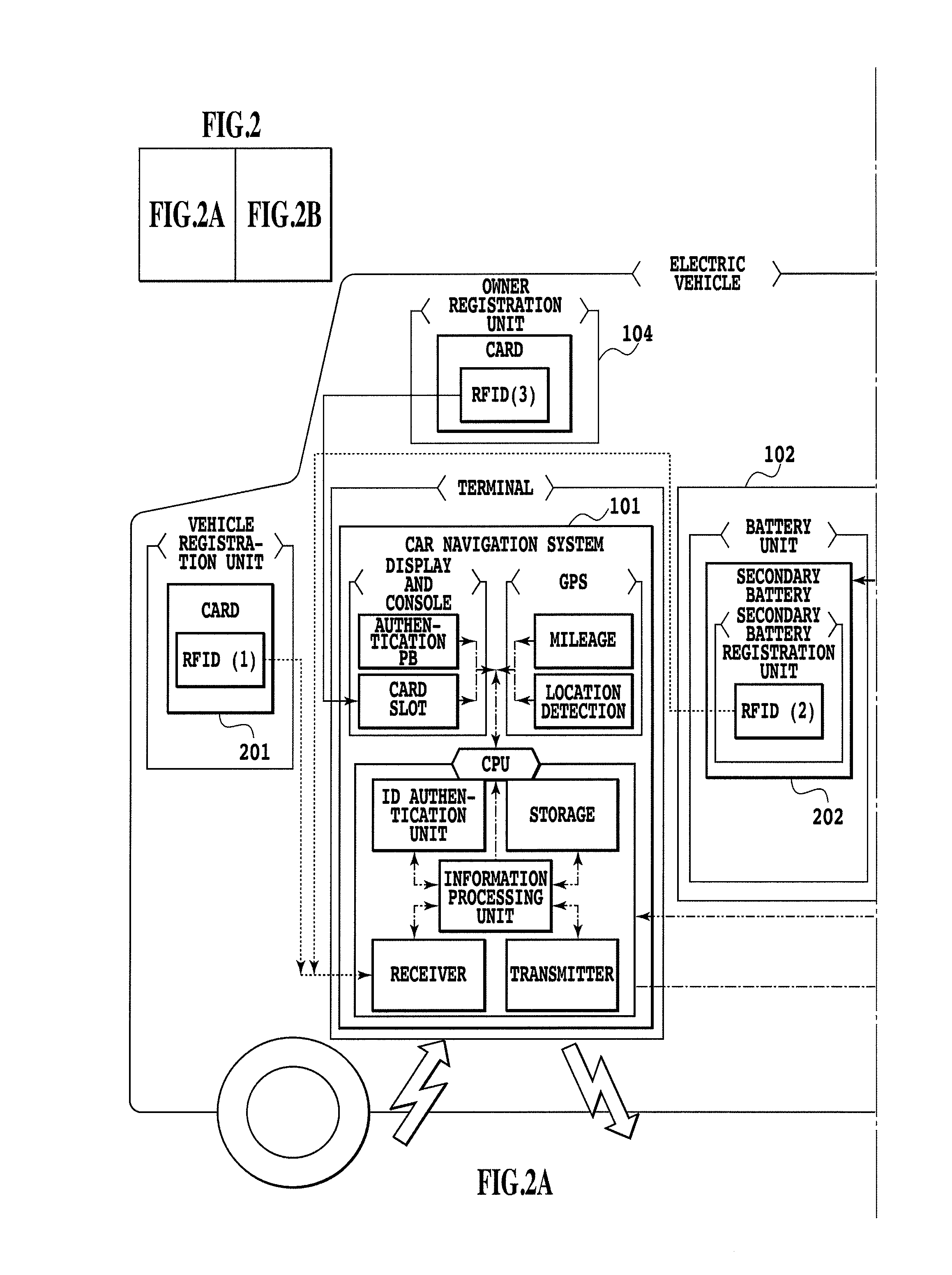
[0075]Although the above-mentioned first and second embodiments implement various functions by using the car navigation system 210, this embodiment is different from these embodiments in that a mobile phone having a data communication function and a GPS function is used as shown in FIG. 6. This embodiment is basically the same as the above-mentioned embodiments in other respects. In other words, in a case of calculating the mileage or the like, or communicating with the management center 120, the management terminal 101 performs the processing by use of the mobile phone. Thereby, even the owner who does not have the car navigation system can use the electric vehicle charging system of the present invention.


PUM

PropertyMeasurementUnit
electric poweraaaaaaaaaa
exhaust emission reductionaaaaaaaaaa
timeaaaaaaaaaa

Abstract

The degrees of exhaust emission suppression and contribution to the environment are evaluated, and a point is added according to the degree of contribution. A system is configured by including an electric vehicle (100), an electric power company (110), a management center (120), a network (130) that connects these, and the like. A battery of the electric vehicle (100) is charged with electric power supplied mainly by the electric power company (110), and various kinds of charge-related information are transmitted to and received from the management center (120) or the like via the network (130) or the like. At the time of charging, the electric vehicle (100) uses wireless communications, for example, to transmit and receive various kinds of data to and from a server (121) via a radio base station (131) and the network (130).

Description

TECHNICAL FIELD[0001]The present invention relates to electrically-driven apparatus charging system and method, and more particularly to electrically-driven apparatus charging system and method which are capable of replenishing electric power required for running, in ordinary households or outdoor charging facilities.BACKGROUND ART[0002]Recently, various types of drive systems such as a hybrid and a fuel cell have been developed and come into practical use even in the field of automobiles where those having mounted therein an engine driven by fossil fuel such as gasoline have heretofore been the mainstream, from the viewpoints of energy saving and environmental protection. Of such automotive drive systems, an electric vehicle runs by charging the vehicle-mounted secondary battery to which electric power is supplied as a power supply from a household power supply provided mainly by an electric power company or the like, or from a charging facility such as a charging station installed...

Claims


Application Information

Patent Timeline
Patent Type & Authority Applications(United States)
IPC IPC(8): G06F19/00B60L11/18G06Q50/00G06Q50/10H01M10/44H02J7/00
CPCB60L2270/12B60L2270/36G06Q30/04H01M10/44Y02T10/7005Y02T90/121B60L53/11Y02T90/14Y02T90/16Y02T10/7072B60L53/14B60L53/60Y02T90/128B60L53/66B60L53/62Y02T90/12Y02T10/70Y02E60/10
Inventor MIZUMACHI, YUTAKA
Owner KYUSHU ELECTRIC POWER CO INC
Learn More