

Pressure detection unit and pressure sensor
a pressure sensor and pressure detection technology, applied in the direction of instruments, device details, piezoelectric/electrostrictive device details, etc., can solve the problems of large current consumption of a/d converters, degraded temperature detecting accuracy, and disadvantageous error generation of stress detecting accuracy, so as to improve the measurement accuracy of pressure sensors and improve temperature detecting accuracy. , the effect of reducing current consumption
- Summary
- Abstract
- Description
- Claims
- Application Information
AI Technical Summary
Benefits of technology
Problems solved by technology
Method used
Image

Examples
first embodiment
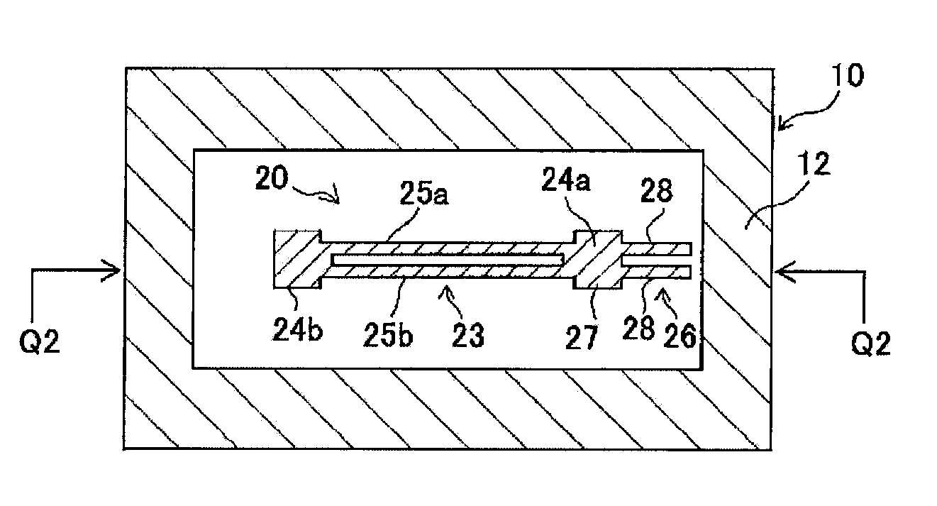
[0092]FIGS. 8A and 8B are schematic views showing a structure of a pressure detection unit 1 according to a first embodiment of the present invention. FIG. 8A is a sectional view taken along a Q2-Q2 line of FIG. 8B. FIG. 8B is a sectional view taken along a Q1-Q1 line of FIG. 8A.
[0093]This pressure detection unit 1 includes a diaphragm 10 which is deformable under pressure, a base 15 which is provided to face the diaphragm 10 and is not deformable under pressure, and a complex resonator element 20 of which a resonance frequency changes according to deformation of the diaphragm 10.
[0094]The complex resonator element 20 includes a first piezoelectric resonator element 23 and a second piezoelectric resonator element 26. The second piezoelectric resonator element 26 is formed to be integrated with a base portion 24a of a pair of base portions 24a and 24b of the first piezoelectric resonator element 23, and resonance frequency of the element 26 changes depending on temperature change.
[00...
second embodiment
[0132]FIGS. 12A to 12C are diagrams showing a structure of a pressure detection unit 2 according to a second embodiment. FIG. 12A is a sectional view of the pressure detection unit 2, FIG. 12B is a plan view of a framed piezoelectric resonator element 30, and FIG. 12C is a lateral view of FIG. 12B. The pressure detection unit 2 includes: the diaphragm 10, the base 15, and the framed piezoelectric resonator element 30. The diaphragm 10 is deformable by pressure. The base 15 is formed to face the diaphragm 10 and is not deformable by pressure. The framed piezoelectric resonator element 30 includes a first piezoelectric resonator element 32 of which a resonance frequency changes in response to deformation of the diaphragm 10 and a second piezoelectric resonator element 35 of which a resonance frequency changes in response to temperature change.
[0133]The diaphragm 10 and the base 15 have the same structures as those of the diaphragm 10 and the base 15 of the pressure detection unit 1 of...
third embodiment
[0145]FIGS. 16A to 16C are diagrams showing a structure of a pressure detection unit 3 according to a third embodiment. FIG. 16A is a sectional view of the pressure detection unit 3, FIG. 16B is a plan view of a framed piezoelectric resonator element 30′, and FIG. 16C is a lateral view of FIG. 16B.
[0146]According to the simulation result of the relationship between shape / dimension of the thin portion 11 and the stress sensitivity of the same shown in FIGS. 15B and 15C, it was proved that increase of the dimension, in the X axis direction, of a pressure detection unit was effective in increasing the stress sensitivity. FIG. 16B shows a structure in which the second piezoelectric resonator element (tuning fork type quartz crystal vibrating element) 35 is connected with the outer frame 31 in the X axis direction. On the other hand, in the framed piezoelectric resonator element 30 shown in FIG. 12B, the second piezoelectric resonator element 35 is provided so as to be connected with the...
PUM
| Property | Measurement | Unit |
|---|---|---|
| current | aaaaa | aaaaa |
| current | aaaaa | aaaaa |
| angle | aaaaa | aaaaa |
Abstract
Description
Claims
Application Information