Nanofluidic preconcentration device in an open environment

a technology of nano-fluoroquinoline and preconcentration device, which is applied in the direction of fluid pressure measurement, liquid/fluent solid measurement, peptide measurement, etc., can solve the problems of mass spectrometry (ms), limiting the delivery of such high-concentrated samples to a desired location, and affecting the extraction of concentrated plugs

Inactive Publication Date: 2010-07-29
MASSACHUSETTS INST OF TECH
View PDF1 Cites 15 Cited by
  • Summary
  • Abstract
  • Description
  • Claims
  • Application Information

AI Technical Summary

Benefits of technology

[0005]In one embodiment, this invention provides a new method of concentrating low-abundance molecular species using the CP-enabled preconcentration process, but within a droplet on a surface. By having a droplet in between an inlet microchannel and an outlet microchannel, the droplet itself acts as a droplet chamber to concentrate low-abundance species. In one embodiment, this invention demonstrates an electrokinetic preconcentration process inside the droplet using fluorescence dye, thus successfully proving the concept of such device. After preconcentration, the accumulated molecules can be detected using conventional immunoassays and other techniques (MALDI-MS or ELISA), without the need for integrating the detectors to the microfluidic system directly.
[0030]In one embodiment, the array further comprising at least one supporting structure positioned between the concentration units, which aids in separating, fixing, stabilizing and keeping a desired distance between the concentration units.
[0031]In one embodiment, the array further comprising at least one supporting structure positioned between the concentration units and the substrate, which aids in suspending the concentration units over the substrate, at a desired height.
[0060]In one embodiment, the surface of the conduit and / or the sample or buffer microchannels or buffer reservoir has been functionalized to enhance the operation efficiency of the device.
[0076]In one embodiment, the array further comprising at least one supporting structure positioned between the concentration units, which aids in separating, fixing, stabilizing and keeping a desired distance between the concentration units.
[0077]In one embodiment, the array further comprising at least one supporting structure positioned between the concentration units and the substrate, which aids in suspending the concentration units over the substrate at a desired height and in bringing the concentration units in contact with the substrate.

Problems solved by technology

Due to the low abundance of most information-rich bio / chemical species to be detected, the amplification / preconcentration of such species has become the most important issues in bioanalytical research and industry.
Due to the extremely high concentration gradient after preconcentration procedure, diffusion and dispersion inside the microchannel are critical, limiting the delivery of such high concentrated sample to a desired location such as mass spectrometry (MS) and matrix-assisted laser desorption / ionization-MS (MALDI-MS) systems.
In this manner, dispersionless extraction of the concentrated plug has been an important issue.
In this manner, many researchers tried detecting samples inside the channel rather than taking it out, but this limits the usage of the concentration device.
However, implementing immunoassay within a microchannel is generally challenging, especially due to issues related to surface chemistry to immobilize antibodies and other chemical reagents required for immunoassays.

Method used


Image

  • Nanofluidic preconcentration device in an open environment
  • Nanofluidic preconcentration device in an open environment
  • Nanofluidic preconcentration device in an open environment

Examples


example 1

High Performance Preconcentrator

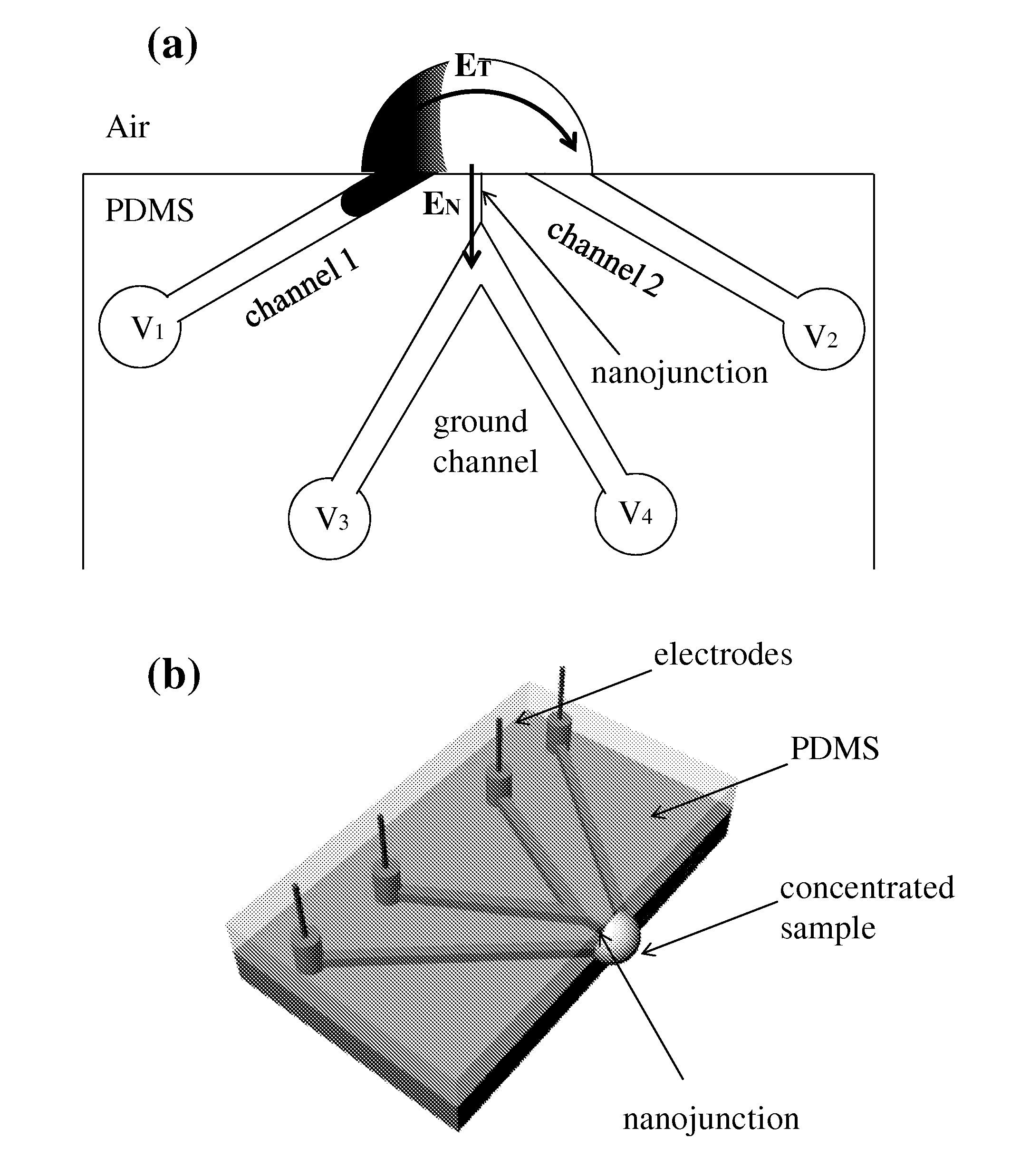
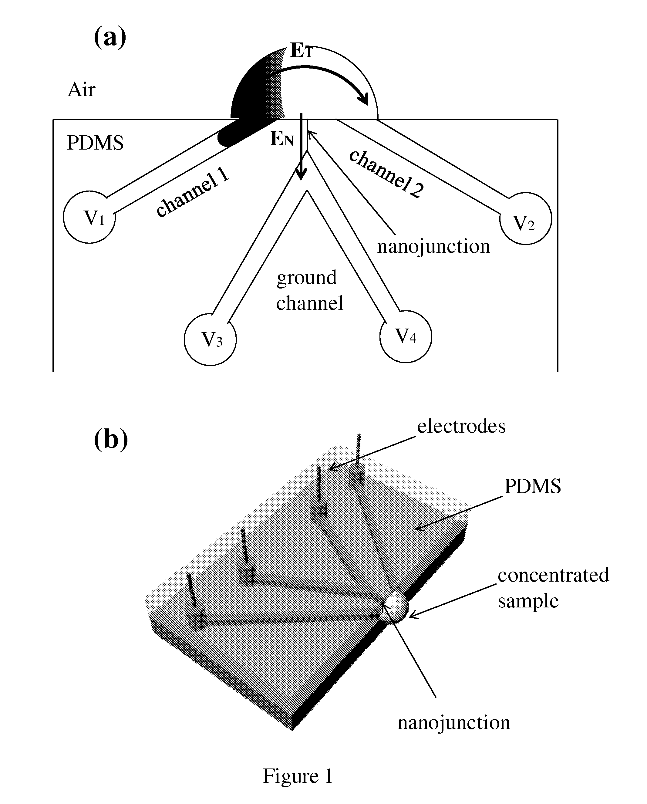
[0324]As shown in FIG. 1(a), two microchannels (channel 1 and channel 2) are open to the outside of the PDMS chip. Injecting sample liquid from either channel 1 or channel 2 can create droplet that can connect two channels. Ground channel, which buried inside the PDMS chip, is connected to the droplet through via nanojunction. Once DC was applied with depletion voltage conditions (V1=V2=V and V3=V4=0), CP was initiated and the ionic concentration in anodic side started to deplete (ion depletion zone) with the normal electric field (EN) through nanochannel. Then adjusting V2 lower than V1 (preconcentration voltage condition) gives tangential electric field (ET) through the droplet. With the application of the tangential electric field (ET), any charged species would accumulate and form a preconcentrated plug inside the droplet. The electric potential can be applied by the electrodes as shown in FIG. 1(b). This preconcentration voltage condition can als...

example 2

High Concentration Drop Dispenser

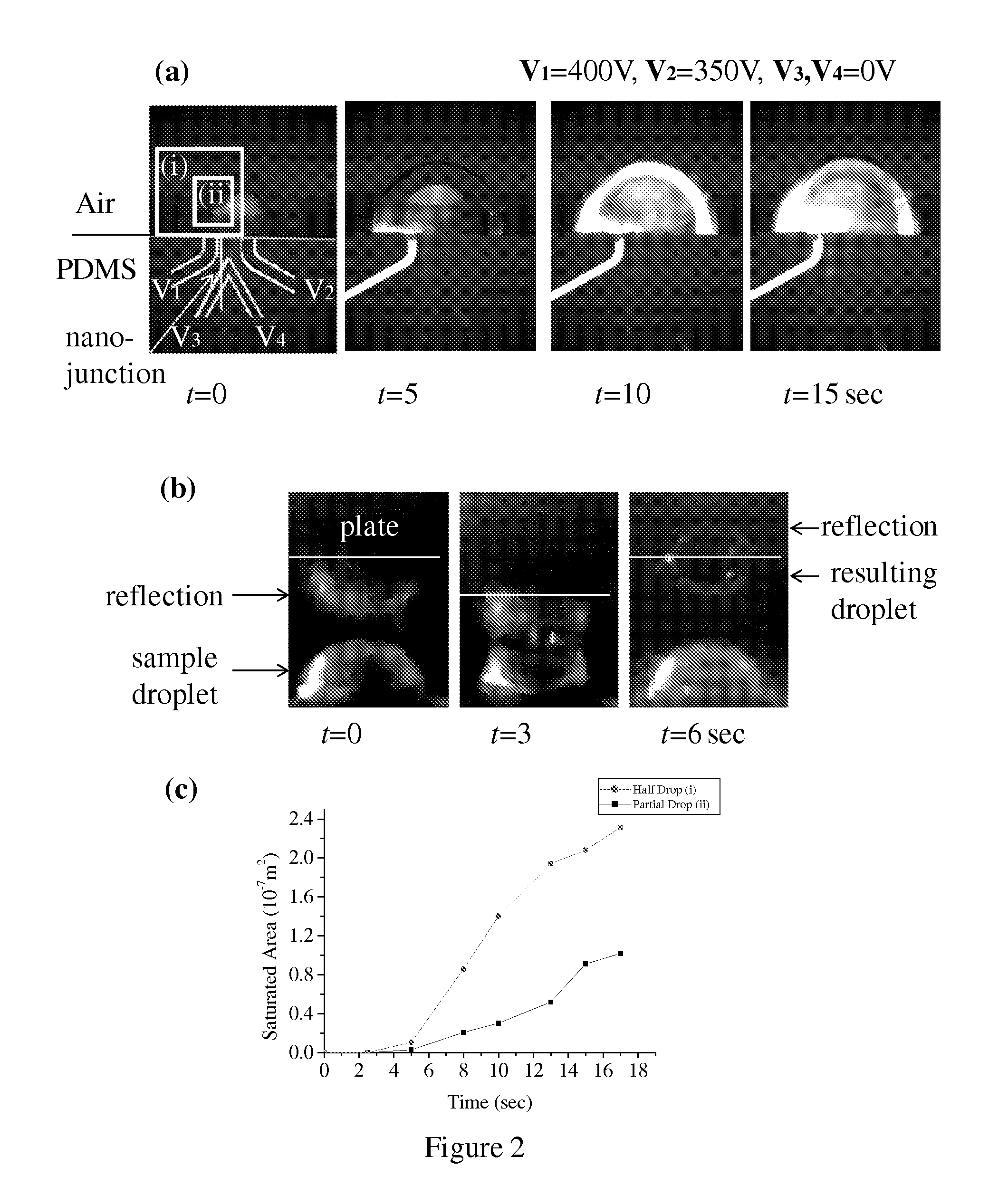
[0326]A microfluidic device is constructed. Due to its microscale size, the droplet on the PDMS chip has a hemispherical shape. With upper plate or objects touching the droplet, droplet changes itself into a liquid bridge. By moving the plate away, liquid bridge breaks apart into two droplets, splitting the samples into two (FIG. 2 (b)). In this method, concentrated sample transfers directly to the target plate without any driving force for transporting (external pressures or electric fields), restricting plug dispersion or electrodiffusion. Also, it can be easily integrated into a massively parallel sensor array (FIG. 3(a)) since the sample droplets locate at the edge of the device.

[0327]In addition to this, the parallelization can be done even without dispensing process as shown in FIG. 3(b). Microchannels in PDMS are bonded to large glass rather than PDMS itself so that the resulting droplets would be quarter spherical shape and directly react wit...


PUM

PropertyMeasurementUnit
depthaaaaaaaaaa
diameteraaaaaaaaaa
diameteraaaaaaaaaa

Abstract

This invention provides a device and methods for increasing the concentration of a charged species in solution, wherein the solution containing the concentrated species is exposed to the environment. Such solution can be formed on a surface or on a tip of a measurement device. The open-environment concentration technique overcomes the disadvantages of in-channel concentration devices, especially by eliminating flow-induced delivery processes that lead to concentration losses. Combined with direct contact dispensing, methods of this invention can be used for various applications such as immunoassay and MALDI-MS.

Description

CROSS REFERENCE TO RELATED APPLICATIONS[0001]This Application claims the benefit of U.S. Provisional Application Ser. No. 61 / 117,506, filed Nov. 24, 2008, which is hereby incorporated by reference in its entirety.GOVERNMENT INTEREST STATEMENT[0002]This invention was made in whole or in part with government support under Grant Number NIH 5-R01-CA119402-04 and under Grant number 5-R01-EB005743-04, awarded by the National Institutes of Health. The government has certain rights in the invention.BACKGROUND OF THE INVENTION[0003]Due to the low abundance of most information-rich bio / chemical species to be detected, the amplification / preconcentration of such species has become the most important issues in bioanalytical research and industry. Considerable improvement in the non-genomic preconcentration methods have been achieved in the last decade, leading at least 100-1000 fold accumulation in sensitivity. Available methods include physical filtration and various novel approaches were studi...

Claims


Application Information

Patent Timeline
Patent Type & Authority Applications(United States)
IPC IPC(8): G01N27/447
CPCB01L3/50273G01N27/44791B01L2400/0421B01L2400/0418Y10T137/2224
Inventor HAN, JONGYOONKIM, SUNG JAEMOON, DUSTIN
Owner MASSACHUSETTS INST OF TECH
Why Eureka
Try Eureka