Handle for container, handle-equipped container, and method for manufacturing handle and container

a technology for handling containers and containers, applied in the direction of manufacturing tools, containers preventing decay, sealing, etc., can solve the problems of inability to directly perform heat setting, insufficient volumetric efficiency improvement, and inability to solve the problem of resolving means, so as to achieve uniform thickness, improve blow molding properties, and ensure the effect of stability

Inactive Publication Date: 2010-07-29
TOYO SEIKAN KAISHA LTD
View PDF5 Cites 9 Cited by
  • Summary
  • Abstract
  • Description
  • Claims
  • Application Information

AI Technical Summary

Benefits of technology

[0068]The handle-equipped container of the present invention has exceptional storability because the transverse cross-section of the body part is substantially quadrangular in shape. The parting line of a blow-molding mold can be oriented in the direction of the diagonal line of the transverse cross-sectional shape in order to attach the handle along the diagonal line, and designs on the various surfaces can be produced without restriction. If the handle-attaching convexity is provided to the concavity, and the handle is attached with a gap being provided between the handle and the wall that surrounds the convexity for attaching the handle, then blow-molding properties will be improved by the gap between the handle and the wall in the concavity that surrounds the convexity for attaching the handle. As a result, the container and the handle will undergo no incidence of separation, wrinkling, cracking, deformation, thickness irregularities caused by unsuitable stretching, or other anomalies. Additionally, uniform thickness due to suitable stretching will result; i.e., the thickness will correspond to the need for strength. Sufficient strength will be obtained, even against drop impact. If the container and handle are both made of polyester, an exceptional effect is obtained in regard to recyclability.
[0069]If the distance between opposite corner parts is gradually made to narrow towards the base part in the bottom half part of the container below the position where the handle is attached, the thickness distribution in the vicinity of the base part can be improved.
[0070]If regions of the blow-molding mold that can contact the handle are treated so as to be heat-insulated during insert molding, it will be possible to prevent the handle from adhering to the mold, or to prevent any occurrence of deformation, whitening, heat degradation, or the like.
[0071]Making the cross-sectional shape of the holding part of the handle into the shape of an “H” allows the weight of the handle to be reduced. Making the plate inside the holding part narrower than the exterior plate has the effect of reducing the likelihood of the fingers, when gripping the holding part, coming into contact with the interior plate, and facilitates holding the handle.
[0072]The longitudinal compression strength of the container can be improved by providing a longitudinal rib on a corner part of body part that connects to the bottom of the handle that is attached to the container.
[0073]When the handle-equipped container of the present invention is configured as a heat-resistant container, the handle will not come loose even when the contents are filled at a high temperature, and a container having good heat resistance can be obtained because the wall that surrounds the handle-attaching convexity will be heat set.

Problems solved by technology

However, in the examples, mention is only made of the body part having a round cross-sectional shape, and no mention is made in regard to an object of obtaining an angular handle-equipped container, nor to resolving means.
The body part of the heat-resistant handle-equipped container of Prior Art Document 2 has a quadrangular cross section below the position where the handle is attached; however, the upper part where the handle is attached has a round cross-section, which is inadequate for improving volumetric efficiency.
Therefore, heat setting cannot be directly performed, and a concern arises in that the strength with which the handle is attached will decline as a result of contraction and deformation during high temperature filling.

Method used


Image

  • Handle for container, handle-equipped container, and method for manufacturing handle and container
  • Handle for container, handle-equipped container, and method for manufacturing handle and container
  • Handle for container, handle-equipped container, and method for manufacturing handle and container

Examples


embodiment 1

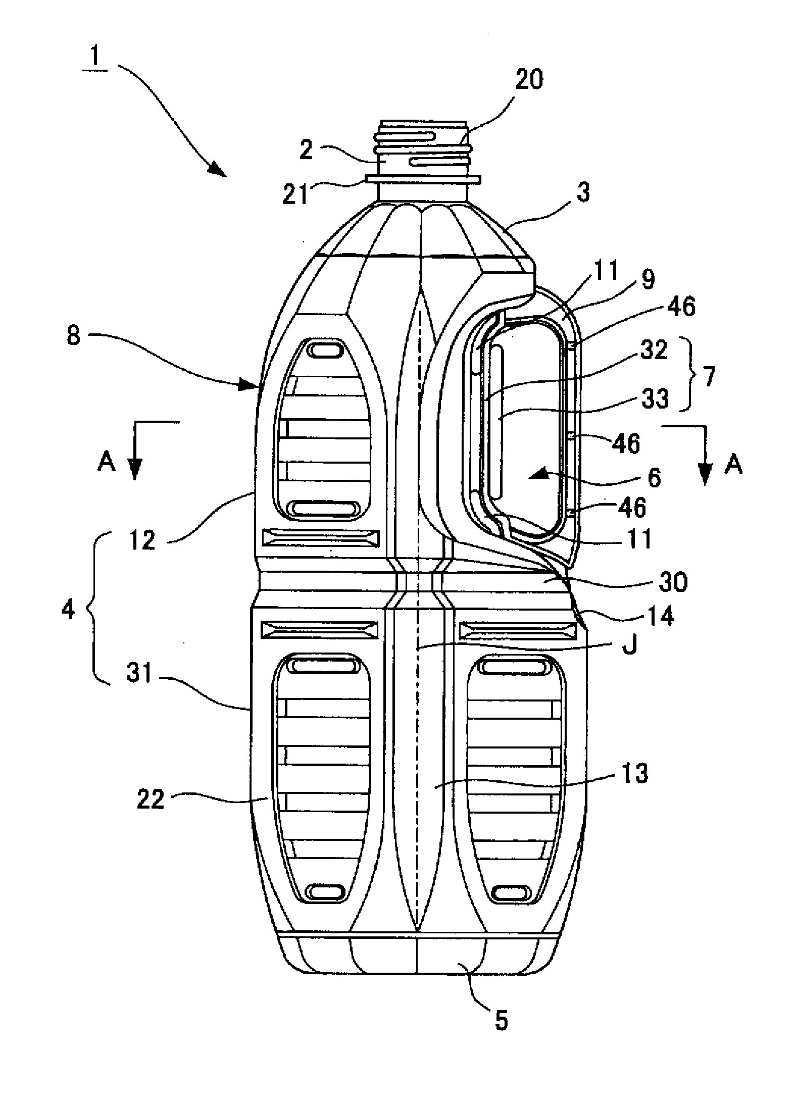
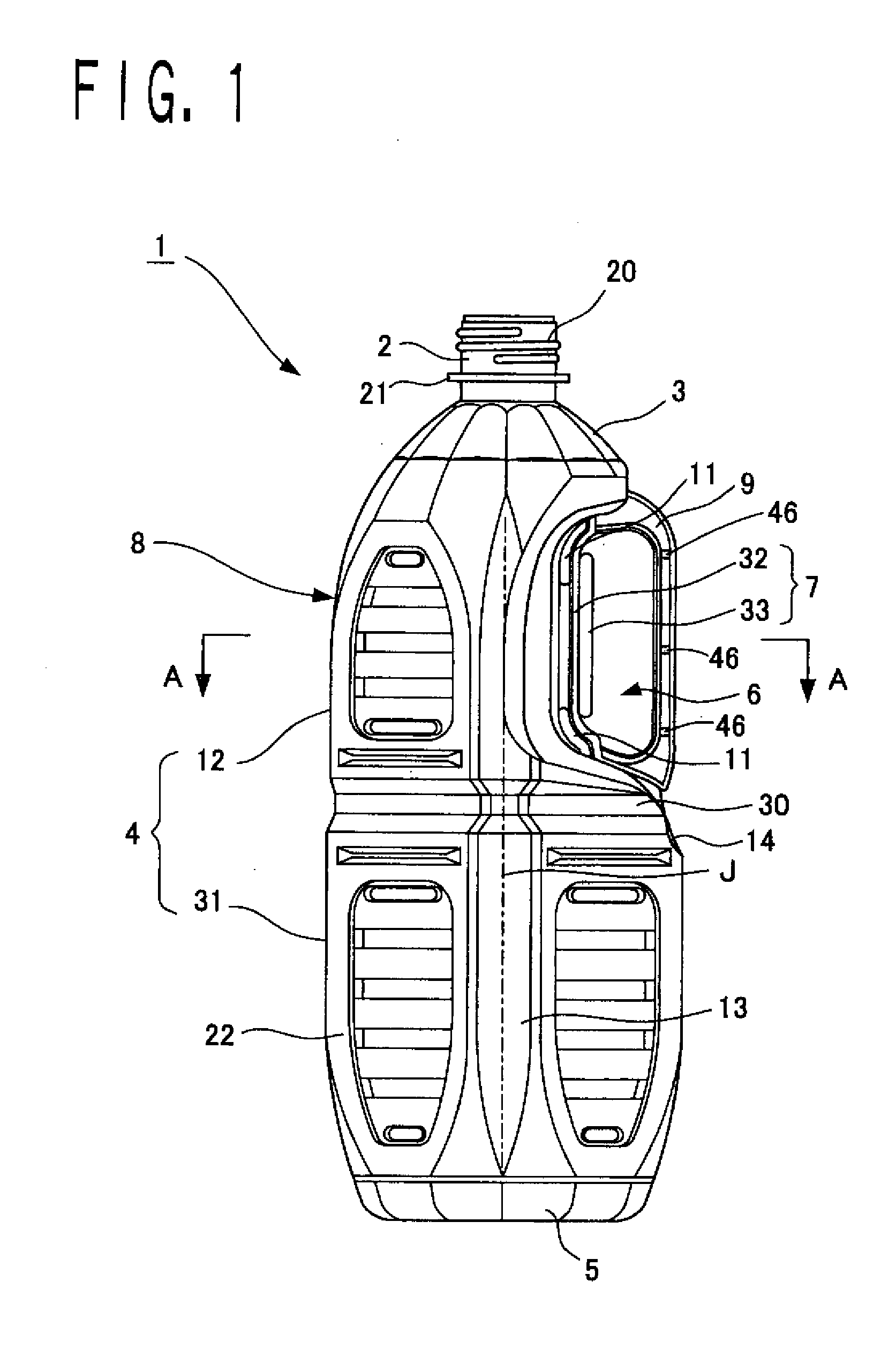
[0077]FIG. 1 is a side view of a handle-equipped container (heat-resistant handle-equipped container) that shows an embodiment of the present invention. FIG. 2 is a cross-sectional view across line A-A in FIG. 1. FIG. 3 is a front view of the handle-equipped container. FIG. 4 is a cross-sectional view across line B-B in FIG. 3. FIG. 5 is an enlarged drawing that shows a panel shape of an end surface of a handle-attaching convexity. FIG. 6 is a rear view of the handle. FIG. 7 is a side view of the handle. FIG. 8 is a cross-sectional view across line X-X in FIG. 7.

[0078]In the drawings, a handle-equipped container 1 comprises a polyester container 8 and a polyester handle 9. The polyester container 8 has a finish part 2, a shoulder part 3, a body part 4, and a base part 5 in the stated order from the top part. A concavity 6 is provided to a portion of the body part 4. A handle-attaching convexity 7 is provided to the concavity 6. The polyester handle 9 is attached to the handle-attach...


PUM

PropertyMeasurementUnit
temperatureaaaaaaaaaa
thicknessaaaaaaaaaa
thicknessaaaaaaaaaa

Abstract

The present invention provides a handle for a container, a handle-equipped container, and a method for manufacturing same. It is accordingly possible to provide a container that has a cross-sectional shape that is substantially quadrangular and allows for exceptional storability, has favorable blow-molding properties, presents none of a variety of anomalies in the container and the handle, and has adequate strength to withstand drop impact.The present invention is characterized in comprising a polyester container, which has a finish part, a shoulder part, a body part, and a base part in the stated order from a top part; which has a concavity provided to a portion of the body part; and which has a handle-attaching convexity provided to the concavity; and a polyester handle attached to the handle-attaching convexity of the container. A space is provided between the handle and a wall surface that surrounds the handle-attaching convexity in the concavity. A transverse cross-sectional shape of the body part has a substantially quadrangular shape. The concavity is in a corner part of an upper half part of the body part, and the handle-attaching convexity is positioned in a concavity along a diagonal line L of the upper half part.

Description

TECHNICAL FIELD[0001]The present invention relates to a handle-equipped container that can be filled with tea or other liquids, and in particular to a heat-resistant handle-equipped container that can be filled with a high-temperature liquid without deforming the container, and a method for manufacturing the container. The invention more particularly relates to a handle-equipped container and method for manufacturing same, wherein a transverse cross-sectional shape of a body part is made substantially quadrangular, and a space is provided between a handle and a wall surface that surrounds a convexity for attaching the handle in a concavity, whereby the blow-molding properties are improved, which creates no incidence of separation between the container and the handle, wrinkling, cracking, irregular thickness caused by deformation or inappropriate stretching, or other anomalies.[0002]The present invention further relates to a handle for a container that can be ideally used on the abov...

Claims


Application Information

Patent Timeline
Patent Type & Authority Applications(United States)
IPC IPC(8): B65D23/10B65D1/02B29C49/20
CPCB29C49/20B29C2049/2039B65D23/106B29K2667/00B29L2031/7158B29K2067/00B29C49/42832B29C49/6605B65D23/10B65D1/02
Inventor MIURA, MASAKI
Owner TOYO SEIKAN KAISHA LTD
Why Eureka
Try Eureka