Optical film, polarizing plate and image display device

a technology of optical film and polarizing plate, which is applied in the direction of polarising elements, instruments, synthetic resin layered products, etc., can solve the problems of difficult to decrease the refractive index, decrease of coating strength or adhesion at the interface, and decrease of scratch resistance, so as to improve film strength and reduce adhesion, the effect of low refractive index

Inactive Publication Date: 2007-10-18
FUJIFILM CORP
View PDF8 Cites 15 Cited by
  • Summary
  • Abstract
  • Description
  • Claims
  • Application Information

AI Technical Summary

Benefits of technology

[0005]One aspect of the present invention is to provide an optical film (preferably antireflection film) using a material with a high fluorine content so as to more reduce the refractive index of the low refractive index layer and being excellent in properties of low reflectance, scratch resistance and marker wiping durability. Another aspect of the present invention is to provide an optical film (preferably antireflection film) using a material with a high fluorine content and exhibiting good stability without worsening the scratch resistance when stored for a long time. Still another aspect of the present invention is to provide a polarizing plate and an image display device each using such an optical film.
[0026]In the optical film of the present invention, a fluorine-containing compound having a fluorine content of 40% or more and a fine particle having a specific particle size are used, whereby an optical film having a low refractive index and at the same time, being improved in the scratch resistance can be provided. In a certain embodiment, the optical film of the present invention is improved in the film strength and the reduction of adhesion at the interface and excellent in both the scratch resistance and the long-term storability. The polarizing plate using the optical film of the present invention is assured of low reflectance and excellent scratch resistance. Furthermore, the display device comprising the optical film or polarizing plate of the present invention is reduced in the reflection of outside light or scenery and assured of remarkably high visibility and excellent scratch resistance.

Problems solved by technology

However, use of a crosslinking material having a high fluorine content tends to incur decrease of the coating strength or adhesion at the interface and in turn, decrease of the scratch resistance.
In this way, it is difficult to decrease the refractive index and at the same time, satisfy the scratch resistance, scratch resistance after long-term storage and antifouling property.

Method used


Image

  • Optical film, polarizing plate and image display device
  • Optical film, polarizing plate and image display device
  • Optical film, polarizing plate and image display device

Examples


example 1

[Production of Antireflection Film]

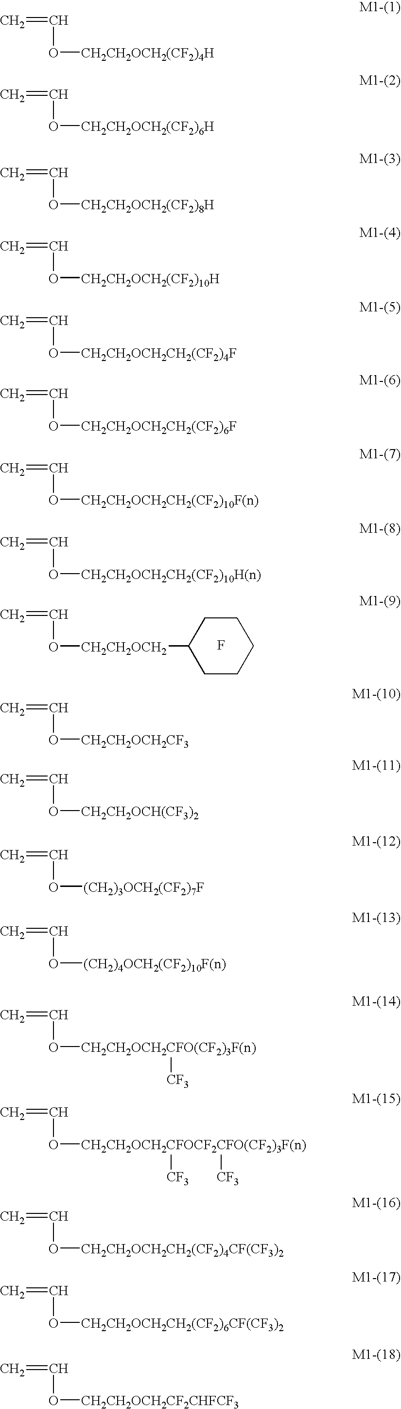
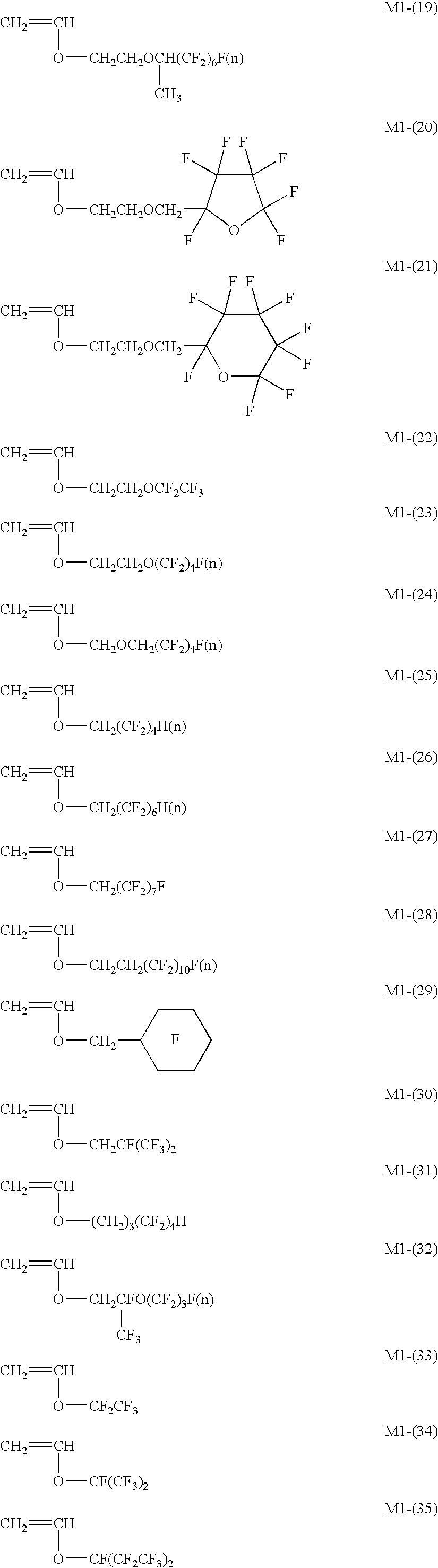
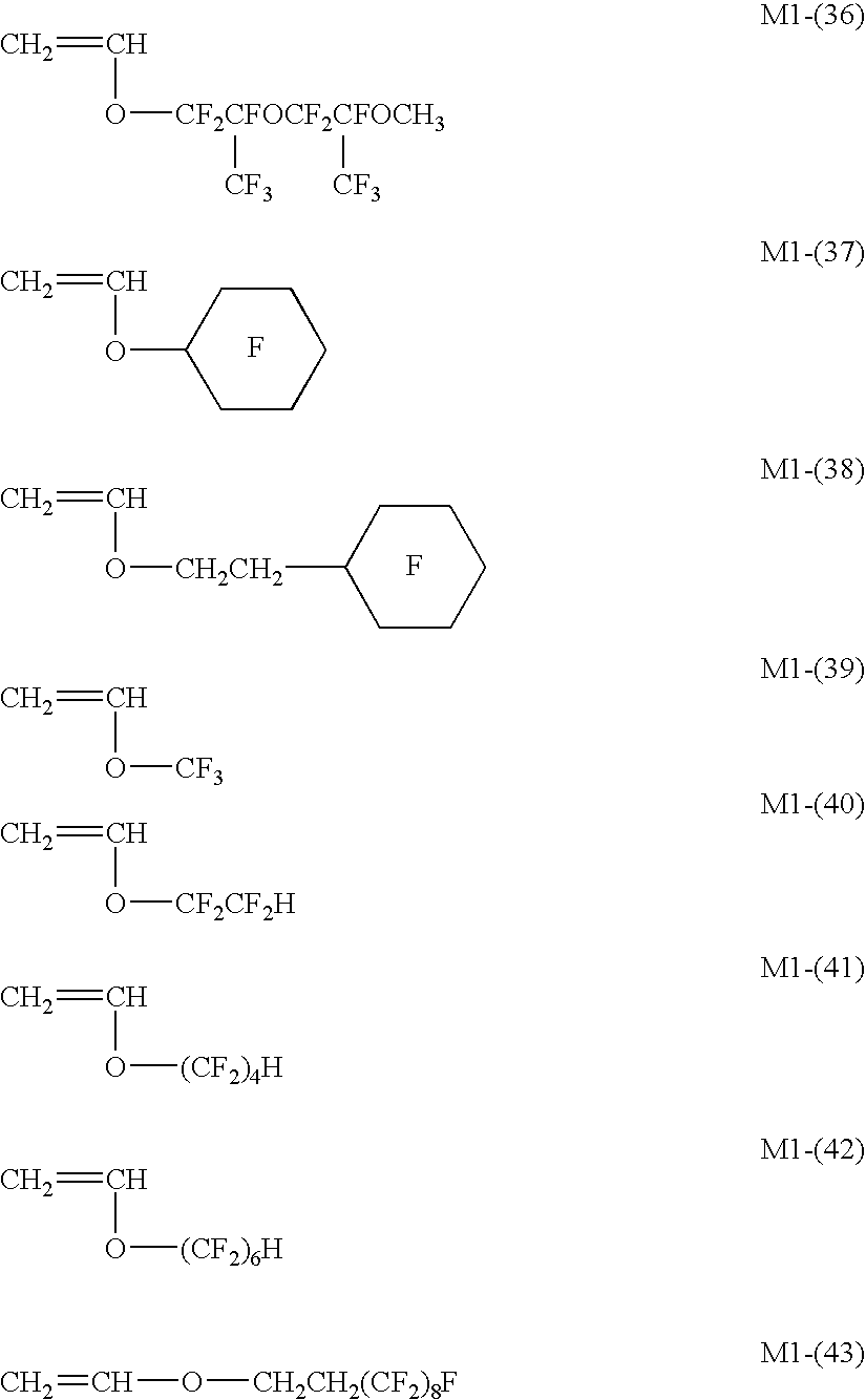
[Preparation of Coating Solutions (Ln-1 to Ln-22) for Low Refractive Index Layer]

[0536]Respective components were mixed as shown in the Table and dissolved in MEK to prepare a coating solution for low refractive index layer having a solid content of 6%.

TABLE 3Fluorine-ContainingPolyfunctionalPolymerCompoundCuring CatalystPhotoinitiatorCoatingAmountFluorineAmountAmountAmountSolution No.KindUsedContent %KindUsedKindUsedKindUsedRemarksLn-1P-440.060.4Cymel 3038.0Catalyst 40501.0PM980M0.4InventionLn-2″44.060.4″8.0″1.0″0.4InventionLn-3″48.060.4″8.0″1.0″0.4InventionLn-4″48.060.4″8.0″1.0—0.0InventionLn-5″55.060.4″8.0″1.0PM980M0.4InventionLn-6″84.060.4″8.0″1.0″0.4ComparisonLn-7″92.060.4″8.0″1.0—0.0ComparisonLn-8″54.060.4″8.0″1.0PM980M0.4ComparisonLn-9″39.060.4″8.0″1.0″0.4InventionLn-10″39.060.4″8.0″1.0″0.4InventionLn-11″40.060.4″8.0″1.0—0.0InventionLn-12″44.060.4″8.0″1.0PM980M0.4InventionLn-13compound for40.038.9″8.0″1.0″0.4ComparisoncomparisonLn-14compound...

example 2

[0576]Coating Solutions Ln23, Ln24 and Ln25 for Low Refractive Index Layer were prepared in the same manner as Coating solution Ln1 for Low Refractive Index Layer except for changing the kind of the photoinitiator to Irg184, Irg907 and Irg369, respectively. After a low refractive index was coated on HC-1 by using Coating Solutions Ln1, Ln23, Ln24 and Ln25 under the same conditions as in Antireflection Film 1, saponification was performed to obtain Antireflection Films 23 to 26.

[0577]Also, Antireflection Films 27 and 28 were obtained by performing the curing and saponification under the same conditions as in the production of Antireflection Film 1 using Coating Solution Ln1 for Low Refractive Index Layer of Example 1 except for changing the temperature at the UV curing to 30° C. and 90° C.

[Evaluation of Antireflection Film]

[0578]Using the saponified antireflection films obtained in this way, the average reflectance, steel wool scratch resistance, marker wiping durability and SW scrat...

example 3

Preparation of Coating Solution for HC Layer:

[0580]

(Composition of Coating Solution HCL-2 for Hardcoat Layer)PETA40 wt %DPHA35 wt %Irgacure 184 3 wt %MX-60012 wt %KBM-510310 wt %Solid content concentration30 wt %MIBK / MEK90 / 10

(Composition of Coating Solution HCL-3 for Hardcoat Layer)PETA40 wt %DPHA38.5 wt %  Irgacure 184 3 wt %SX-3505.5 wt % Crosslinked acryl-styrene particle 3 wt %KBM-510310 wt %Solid content concentration30 wt %MIBK / MEK90 / 10

(Composition of Coating Solution HCL-4 for Hardcoat Layer)PETA40 wt %DPHA31 wt %Irgacure 184 3 wt %SX-35010 wt %Crosslinked acryl-styrene particle5.5 wt % KBM-510310 wt %Solid content concentration30 wt %MIBK / MEK90 / 10

[0581]The constituent components above are shown by the mass percentage of the solid content. Details of the compounds used are as follows.

PETA:

[0582]A mixture of pentaerythritol triacrylate and pentaerythritol tetraacrylate, produced by Nippon Kayaku Co., Ltd.

DPHA:

[0583]A mixture of dipentaerythritol pentaacrylate and dipentaerythr...


PUM

PropertyMeasurementUnit
refractive indexaaaaaaaaaa
particle sizeaaaaaaaaaa
refractive indexaaaaaaaaaa

Abstract

An optical film including a support and a layer provided by applying a coating composition as an outermost layer, wherein the coating composition contains a fluorine-containing compound having a fluorine content of 40% by weight or more, and a particle having a particle size of from 5 to 120 nm, and the outermost layer has a refractive index of from 1.20 to 1.38.

Description

FIELD OF THE INVENTION[0001]The present invention relates to an optical film, a polarizing plate using the optical film, and an image display device using the optical film or the polarizing plate.BACKGROUND OF THE INVENTION[0002]In an image display device such as cathode ray tube display (CRT), plasma display panel (PDP), electroluminescent display (ELD) and liquid crystal display (LCD), an optical film, particularly, an antireflection film is generally disposed on the outermost surface of the display so as to reduce the reflectance by utilizing the principle of optical interference and thereby prevent the reduction in contrast due to reflection of outside light or prevent the reflection of an image.[0003]The antireflection film can be produced by forming, on a support, a low refractive index layer having a refractive index lower than that of the support to have an appropriate thickness. In order to realize a low reflectance, a material having a refractive index as low as possible i...

Claims


Application Information

Patent Timeline
Patent Type & Authority Applications(United States)
IPC IPC(8): B32B5/16B32B27/30B32B27/18B32B7/02G02B1/10C09D4/02C09D127/12C09D129/10C09D161/20C09D183/10G02B1/11G02B1/111G02B1/14G02B5/30G02F1/1335
CPCY10T428/25G02B1/111Y10T428/31935Y10T428/31663Y10T428/3154Y10T428/249971
Inventor WAKIZAKA, DAIKIYONEYAMA, HIROYUKI
Owner FUJIFILM CORP
Why Eureka
Try Eureka