

Cryogenic propellant depot and deployable sunshield
- Summary
- Abstract
- Description
- Claims
- Application Information
AI Technical Summary
Benefits of technology
Problems solved by technology
Method used
Image

Examples
Embodiment Construction
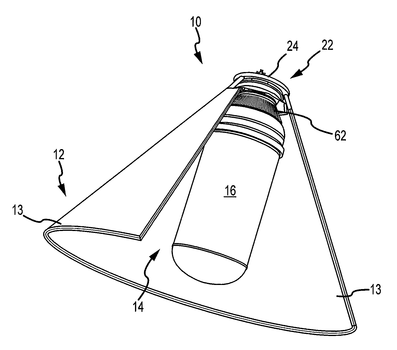
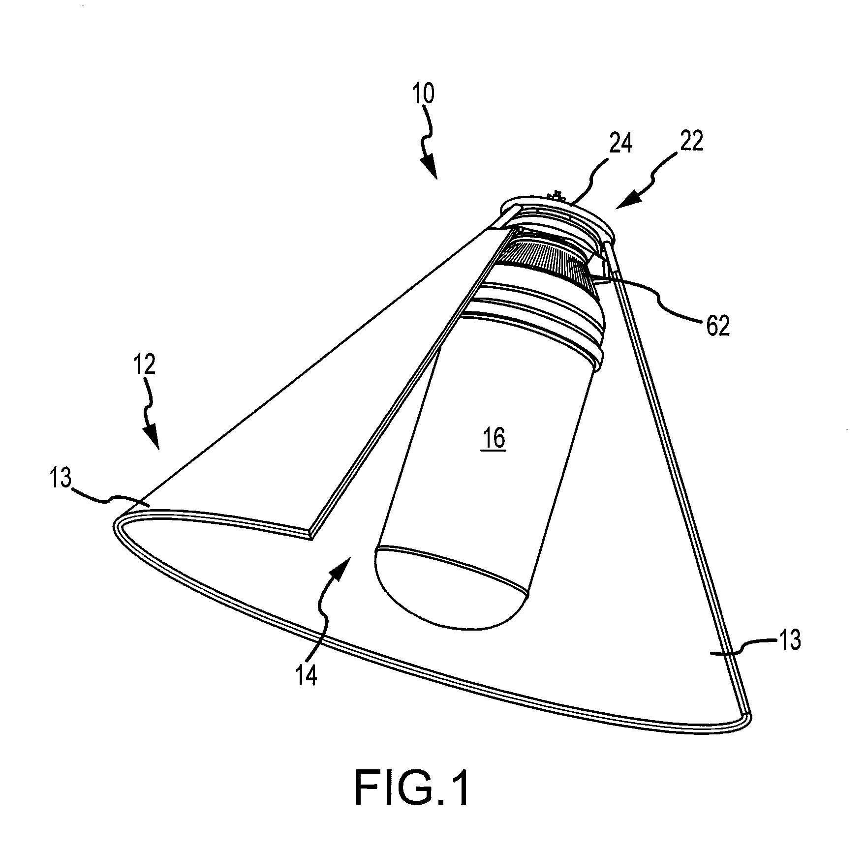
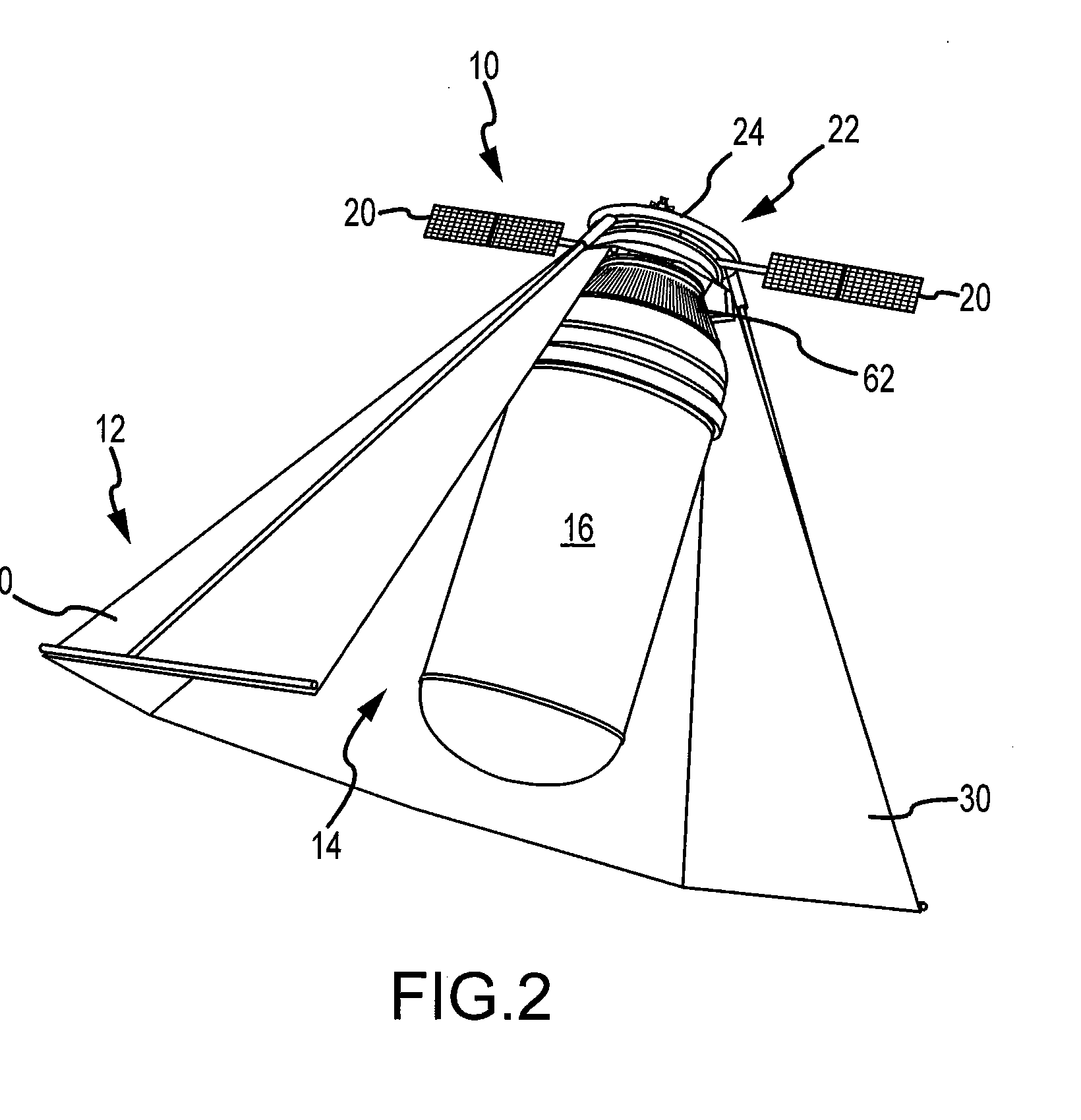
[0032]In accordance with the present invention and in one aspect of the invention, it includes a combination of a cryogenic propellant tank and an integral sunshield. According to this first aspect, the propellant tank can be incorporated as the upper stage of a launch vehicle further including a propulsion system that can carry a payload such as a satellite. In another aspect of the invention as a subcombination, it may be considered a sunshield especially adapted for space vehicles. In yet another aspect of the invention as a subcombination, it may be considered a cryogenic propellant tank placed in orbit and especially adapted for fueling and refueling space vehicles. In another aspect of the invention, a method is provided for deploying a sunshield for a space vehicle. In yet another aspect of the invention, a method is provided for providing a readily accessible liquid within a cryogenic tank while in earth orbit for transfer to another space vehicle.
[0033]FIG. 1 illustrates a ...
PUM
 Abstract
Description
Claims
Application Information