Liquid-crystal display device

a liquid crystal display and liquid crystal display technology, applied in the field of liquid crystal display devices, can solve the problems of additive bleedout, coloration of display images, and increase of haze, and achieve the effect of improving viewing angle characteristics

Active Publication Date: 2010-07-29
FUJIFILM CORP
View PDF10 Cites 3 Cited by
  • Summary
  • Abstract
  • Description
  • Claims
  • Application Information

AI Technical Summary

Benefits of technology

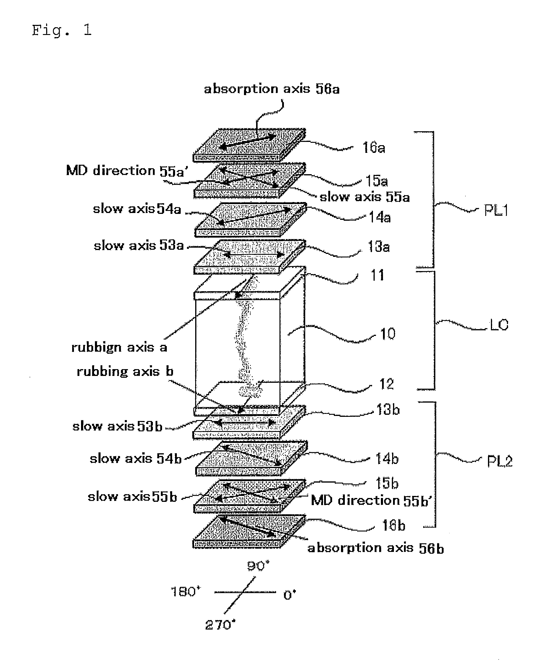
[0204]When Re of the second optically-anisotropic layer disposed on one side of the liquid-crystal cell is not higher than Re of the third optically-anisotropic layer, then it is preferable as improving viewing angle characteristics. Preferably, this condition is satisfied within the whole visible light range.
[0205]Preferably, the second and third optically anisotropic layers are transparent polymer films, and, more specifically, transparent polymer films having a transparency equal to or more than 80%.
[0206]Examples of the polymer film to be used as the second or third optically anisotropic layer include films of cellulose esters such as cellulose acetate and cellulose diacetate; norbornene base polymer films; and polymethyl methacrylate films. Commercially available films are also usable. Examples of the commercially available norbornene base film include ARTON series (by JSR) and ZEONEX series (by Nippon Zeon). Among these, films made of cellulose esters are preferable, and films made of cellulose low-fatty acid esters are more preferable. In the description, the term “low-fatty acid” is used for any C6 or shorter fatty acids. Especially, cellulose acetate (C2), cellulose propionate (C3) and cellulose butyrate (C4) are preferable. The films made of cellulose acetate are especially preferable. Mixed fatty acid esters such as cellulose acetate propionate and cellulose acetate butyrate are also usable.
[0207]Other known polymers such as polycarbonates and polysulfones easily exhibit birefringence, however, their exhibition of birefringence is controllable by modifying molecules as described in WO 00 / 26705 pamphlet. And such polymers may be used as a material for preparing films to be used as the second or third optically anisotropic layer.
[0208]The optical film is used as a protective film of a polarizing element or a retardation film, then it is desirable that a film of cellulose acetate having a degree of acetylation of from 55.0 to 62.5% around is used as the polymer film. More preferably, the degree of acetylation is from 57.0 to 62.0% around. The degree of acetylation as referred to herein means the amount of bonding acetic acid per mass of the cellulose unit.
[0209]The degree of acetylation may be determined through measurement and calculation of the degree of acetylation according to ASTM D-817-91 (test method for cellulose acetate and others).

Problems solved by technology

However, when such an optical film having an optically-anisotropic layer formed by the use of a discotic compound is used for viewing angle compensation in a bend alignment-mode liquid-crystal display device, it has been pointed out that light at a specific wavelength may leak out to cause coloration of display images (see JPA No. hei 11-316378).
In the method of increasing Rth of an optical film, when an additive capable of expressing the optical characteristic is added, then the additive may bleed out and the haze may increase.
With that, the production latitude may decrease and the method is difficult to realize.
In the above, a bend alignment mode is mainly described, but vertical alignment-mode liquid-crystal display devices have the same problems as above.

Method used


Image

  • Liquid-crystal display device
  • Liquid-crystal display device
  • Liquid-crystal display device

Examples


example 1

1. Example 1

1.-1 Formation of Third Optically-Anisotropic Layer

[0300]The following ingredients were put into a mixing tank and stirred under heat to dissolve them, thereby preparing a cellulose acetate solution A.

Formulation of Cellulose Acetate Solution ACellulose acetate having a degree of100mas . pts.acetylation of 60.9%Triphenyl phosphate7.8mas . pts.Biphenyldiphenyl phosphate3.9mas . pts.Methylene chloride300mas . pts.Methanol45mas . pts.

[0301]4 parts by mass of cellulose acetate having a degree of acetylation of 60.9% (linter), 25 parts by mass of a retardation enhancer mentioned below, 0.5 parts by mass of fine silica particles (mean particle size: 20 nm), 80 parts by mass of methylene chloride and 20 parts by mass of methanol were put into another mixing tank and stirred under heat to prepare a retardation enhancer solution.

Retardation Enhancer:

[0302]

[0303]34.4 parts by mass of the retardation enhancer solution was mixed with 470 parts by mass of the cellulose acetate soluti...

examples 2 to 9

2. Examples 2 to 9

[0344]OCB-mode liquid-crystal display devices were produced and evaluated in the same manner as in Example 1, for which, however, the TAC film used as the second optically-anisotropic layer and / or the TAC film used as the third optically-anisotropic layer were replaced with the TAC films having the properties shown in Table 1.

[0345]Re and Rth of the TAC films were controlled by changing the condition in biaxial stretching treatment.

example 10

3. Example 10

[0346]An OCB-mode liquid-crystal display device was produced and evaluated in the same manner as in Example 1, for which, however, the discotic liquid-crystal of the first optically-anisotropic layer was replaced with a rod-like liquid-crystal NG-1 shown below, and the TAC film used for the second optically-anisotropic layer and the TAC film used for the third optically-anisotropic layer were replaced with the TAC films having the properties shown in Table 1.

4. Comparative Examples 1 to 4


PUM

PropertyMeasurementUnit
thicknessaaaaaaaaaa
angleaaaaaaaaaa
thickness-direction retardationaaaaaaaaaa

Abstract

A liquid-crystal display device comprising a liquid-crystal cell and at least three optically-anisotropic layers disposed on each side of the liquid crystal cell, wherein they are combined so that the Δnd value of the liquid-crystal cell and the optical characteristics of the optically-anisotropic layers can satisfy predetermined relationships, is disclosed.

Description

BACKGROUND OF THE INVENTION[0001]1. Technical Field of the Invention[0002]The present invention relates to a liquid-crystal display device, especially to a bend alignment or vertical alignment-mode liquid-crystal display device.[0003]2. Related Art[0004]There has been proposed a liquid-crystal display device (LCD) comprising a bend alignment-mode liquid-crystal cell, in which rod-like liquid-crystal molecules are aligned substantially in opposite directions (symmetrically) in the upper part and the lower part of the liquid-crystal cell (see U.S. Pat. No. 4,583,825 and U.S. Pat. No. 5,410,422). The bend alignment mode is characterized in that, as compared with general liquid-crystal modes such as TN mode and STN mode, the viewing angle is broad and the response speed is high. In addition, since the bend alignment-mode liquid-crystal cell has a self-optical compensatory function, it is referred to as an OCB (optically compensatory bend) liquid-crystal mode.[0005]As a bend alignment-mo...

Claims


Application Information

Patent Timeline
Patent Type & Authority Applications(United States)
IPC IPC(8): G02F1/1347G02F1/13363
CPCG02B5/3083G02F1/1393G02F2001/133635G02F2413/105G02F2413/04G02F2413/08G02F2202/28G02F1/133635
Inventor OHMURO, KATSUFUMINAKAMURA, SHUN
Owner FUJIFILM CORP
Why Eureka
Try Eureka