Turbine arrangement and method of cooling a shroud located at the tip of a turbine blade

a technology of turbine blades and shrouds, which is applied in the direction of machines/engines, stators, liquid fuel engines, etc., can solve the problems of reducing the capability of heat dissipation from the shroud, and achieve the effects of reducing the ability of dissipation of heat, reducing the warming of gas, and improving cooling efficiency

Inactive Publication Date: 2010-07-29
SIEMENS AG
View PDF10 Cites 14 Cited by
  • Summary
  • Abstract
  • Description
  • Claims
  • Application Information

AI Technical Summary

Benefits of technology

[0009]With this arrangement the flow towards the shroud will have a very high velocity. This flow will mix with an overlap leakage through the radial gap between the shroud and the inner wall of the stator. This leakage has a lower velocity in the circumferential direction than the supersonic flow emerging from the supersonic nozzle. Thus, by mixing the leakage flow with the supersonic flow the supersonic flow will increase the circumferential velocity of the mix which will lead to a lower relative velocity in the shroud's rotating frame of reference, whereby the cooling efficiency of the shroud cooling is increased. In contrast thereto, the relative circumferential velocity of the shroud and the gas in the gap between the shroud and the stator is high in the state of the art cooling arrangements. Hence, in such arrangements the friction between the gas and the shroud is high and, as a consequence, the temperature of the gas is increased. This increase lowers the capability of heat dissipation from the shroud.
[0011]A seal is advantageously located in the wall section along which the shroud moves. This seal is partly or fully plain and the supersonic nozzle is located in the plain seal or its plain section if it is only partly plain. Such a plain seal (section) reduces friction between the supersonic flow and the stator wall as compared to non-plain seals.
[0012]The seal in the stator's wall may, in particular, comprise a plain section and a honeycomb section where the honeycomb section is located upstream from the plain section. By this configuration the effectiveness of sealing upstream from the supersonic nozzle can be increased without substantially increasing the friction between the supersonic flow and the stator wall.
[0014]In the inventive method of cooling a shroud located at the tip of a turbine blade of a rotor while the rotor is turning a supersonic cooling fluid flow is provided which has a component in its flow direction that is parallel to the moving direction of the shroud of the turning rotor blade. Such supersonic cooling fluid flow would mix with a leakage flow flowing in the substantially axial direction of the rotor through the gap between the shroud and the inner wall of the stator. The mixture of the supersonic cooling fluid flow and the leakage flow would, as a consequence, have a circumferential velocity component that decreases the relative velocity between the shroud and the gas flow through the gap. The velocity reduction in the turbine frame of reference leads to a reduced warming of the gas in the gap by the movement of the rotating rotor and hence to an improved cooling efficiency as warming the gas by the movement would mean a reduced capability of dissipating heat from the shroud itself.

Problems solved by technology

This increase lowers the capability of heat dissipation from the shroud.

Method used


Image

  • Turbine arrangement and method of cooling a shroud located at the tip of a turbine blade
  • Turbine arrangement and method of cooling a shroud located at the tip of a turbine blade
  • Turbine arrangement and method of cooling a shroud located at the tip of a turbine blade

Examples


Embodiment Construction

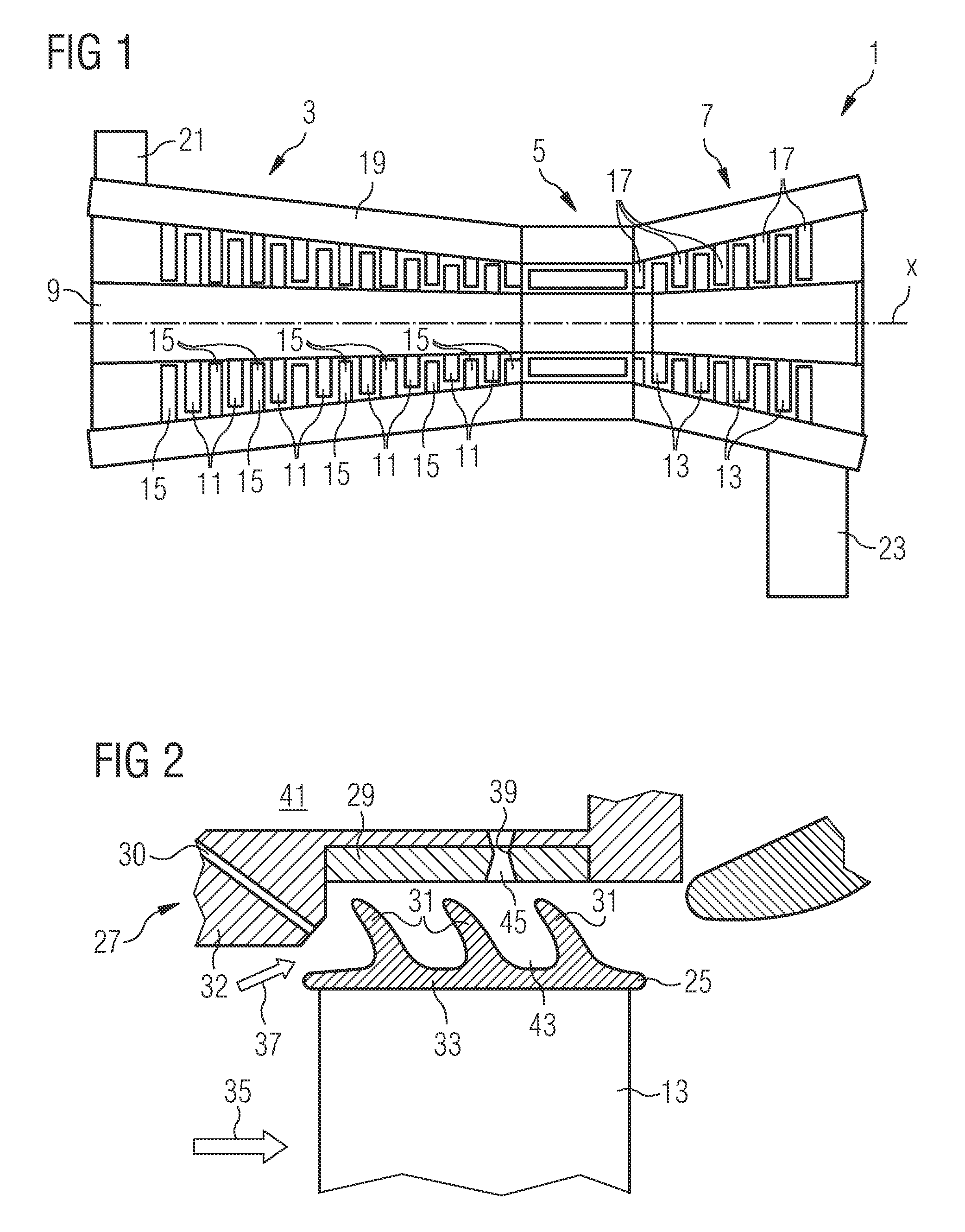
[0021]FIG. 1 shows, in a highly schematic view, a gas turbine engine 1 comprising a compressor section 3, a combustor section 5 and a turbine section 7. A rotor 9 extends through all sections and comprises, in the compressor section 3, rows of compressor blades 11 and, in the turbine section 7, rows of turbine blades 13 which may be equipped with shrouds at their tips. Between neighbouring rows of compressor blades 11 and between neighbouring rows of turbine blades 13 rows of compressor vanes 15 and turbine vanes 17, respectively, extend from a stator or housing 19 of the gas turbine engine 1 radially inwards towards the rotor 9.

[0022]In operation of the gas turbine engine 1 air is taken in through an air inlet 21 of the compressor section 3. The air is compressed and led towards the combustor section 5 by the rotating compressor blades 11. In the combustor section 5 the air is mixed with a gaseous or liquid fuel and the mixture is burnt. The hot and pressurised combustion gas resul...


PUM


Abstract

A turbine arrangement with a rotor and a stator surrounding the rotor forming a flow path for hot and pressurised combustion gases between the rotor and the stator is provided. The rotor defines a radial direction and a circumferential direction and includes turbine blades extending in the radial direction through the flow path towards the stator. The turbine blades have shrouds located at their tips and the stator includes a wall section along which the shrouds move when the rotor is turning. A supersonic nozzle is located in the wall section and is connected to a cooling fluid provider. The supersonic nozzle provides a supersonic cooling fluid flow towards the shroud. The supersonic nozzle is angled with respect to the radial direction towards the circumferential direction in such an orientation that the supersonic cooling fluid flow has a flow component parallel to the moving direction of the shroud.

Description

CROSS REFERENCE TO RELATED APPLICATIONS[0001]This application is the US National Stage of International Application No. PCT / EP2008 / 057709, filed Jun. 18, 2008 and claims the benefit thereof. The International Application claims the benefits of European Patent Office application No. 07012388.0 EP filed Jun. 25, 2007, both of the applications are incorporated by reference herein in their entirety.FIELD OF INVENTION[0002]The present invention relates to a turbine arrangement with a rotor and a stator surrounding the rotor so as to form a flow path for hot and pressurised combustion gases between the rotor and the stator, the rotor comprising turbine blades extending in a substantially radial direction through the flow path towards the stator and having a shroud located at their tips. In addition, the invention relates to a method of cooling a shroud located at the tip of a turbine blade of a rotor while the rotor is turning.BACKGROUND OF INVENTION[0003]Shrouds at the radial outer end o...

Claims


Application Information

Patent Timeline
Patent Type & Authority Applications(United States)
IPC IPC(8): F01D25/12F01D11/08F01D5/22
CPCF01D5/225F01D11/10F05D2250/324F05D2250/323F05D2240/11F01D25/12
Inventor MALTSON, JOHN DAVID
Owner SIEMENS AG
Why Eureka
Try Eureka