Rotor blade

a technology of rotating blades and blades, which is applied in the field of rotating blades, can solve the problems of under-cooling extremities, less effective or efficient cooling of shrouds, and difficult cooling of shrouds, and achieve the effects of improving heat transfer coefficients, increasing the number or size of such passages, and facilitating inspection of passages

Active Publication Date: 2010-07-29
ROLLS ROYCE PLC
View PDF24 Cites 4 Cited by
  • Summary
  • Abstract
  • Description
  • Claims
  • Application Information

AI Technical Summary

Benefits of technology

[0028]The cavity allows many of these first passages to be shorter than the corresponding passages would be in a conventional shroud. Shorter passages tend to have improved heat transfer coefficients at positions close to the outer surface of the shroud.
[0029]Each first passage may extend in a straight line between its exit hole and a corresponding entrance hole at the cavity. This facilitates inspection of the passages for blockages, as a light source positioned in cavity can illuminate all the passages extending in a straight line from the cavity. Also, if increased cooling of the shroud is required it is a relatively simple matter to increase the number or size of such passages. There is little danger that such an increase will cause choking of the flow of cooling air, as there is no intermediate feed conduit between the cavity and the passages in which the flow may become choked. Also pressure losses produced at feed conduit / passage intersections can be avoided.
[0030]The shroud may further have one or more recesses at the outer surface thereof, at least a portion of the first passages having their exit holes at the or each recess. For example, a recess may be positioned at an edge portion of the shroud which, in use, abuts a facing edge portion of the shroud of an adjacent rotor blade, the recess preventing the exit holes thereat from being blocked by the shroud of the adjacent rotor blade. Additionally or alternatively a recess may be positioned at a downstream edge portion of the shroud, where it can reduce thermal stress distributions.
[0031]The shroud may further have one or more second passages, the or each second passage intersecting a plurality of the first passages to allow a flow of cooling air between the intersected first passages. This flow between first passages can help to reduce the growth of boundary layers and thereby improve local heat transfer coefficients.

Problems solved by technology

Typically, most high temperature HP turbine blade shrouds are cooled using a combination of internal convection cooling and film cooling, although the latter may not be very effective or efficient due to the adverse pressure gradients and strong secondary flows that exist on or near the shroud's gas washed surfaces.
As gas temperatures and pressures rise in the engine, such shrouds become more difficult to cool, especially at their extremities, where oxidation and thermal cracking can be problematic.
A difficulty is that the feed conduits and cooling passages are often too long and the coolant picks up too much heat en-route to the edges of the shroud, resulting in under-cooled extremities.
In addition the small diameter cooling passages can suffer from a thickening boundary layer at high length / diameter ratios, causing the heat transfer coefficient to diminish with distance along the passages.
Another problem with conventional shroud cooling configurations is their poor adaptability when there are changes to the thermal boundary conditions of the blade.
For example, if more coolant is required, larger feed conduits may be necessary to pass the increased flow and the shroud geometry has to be made more bulky, particularly in the vicinity of the labyrinth seals and fences.
These changes add mass to the shroud structure and increase aerofoil radial stress levels and reduce creep life.
Conversely, if the feed conduits are not enlarged but the number of cooling passages is increased, the flow can become throttled or choked within the feed conduits and flow levels in the cooling passages can actually fall.

Method used


Image

  • Rotor blade
  • Rotor blade
  • Rotor blade

Examples


Embodiment Construction

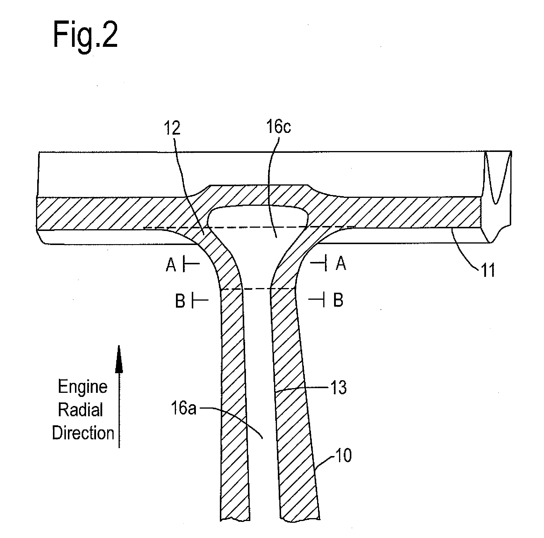
[0046]FIG. 2 shows schematically a cross-section parallel to the engine axis through the radially outer part of a rotor blade according to the present invention. The blade has an airfoil portion 10, a shroud 11 and a fillet portion 12 (whose radially inner and outer boundaries are denoted with dashed lines) which eases the transition from the outer surface of the airfoil portion to the outer surface of the shroud.

[0047]The airfoil portion contains a plurality of internal conduits which carry cooling air through the airfoil portion. The internal conduits are formed during the casting of the blade by respective ceramic cores positioned within the mould for the blade. When the cores are removed by chemical leaching after casting, the voids which they leave behind define the conduits. The airfoil portion 10, shroud 11 and fillet portion 12 can be formed as one-piece casting.

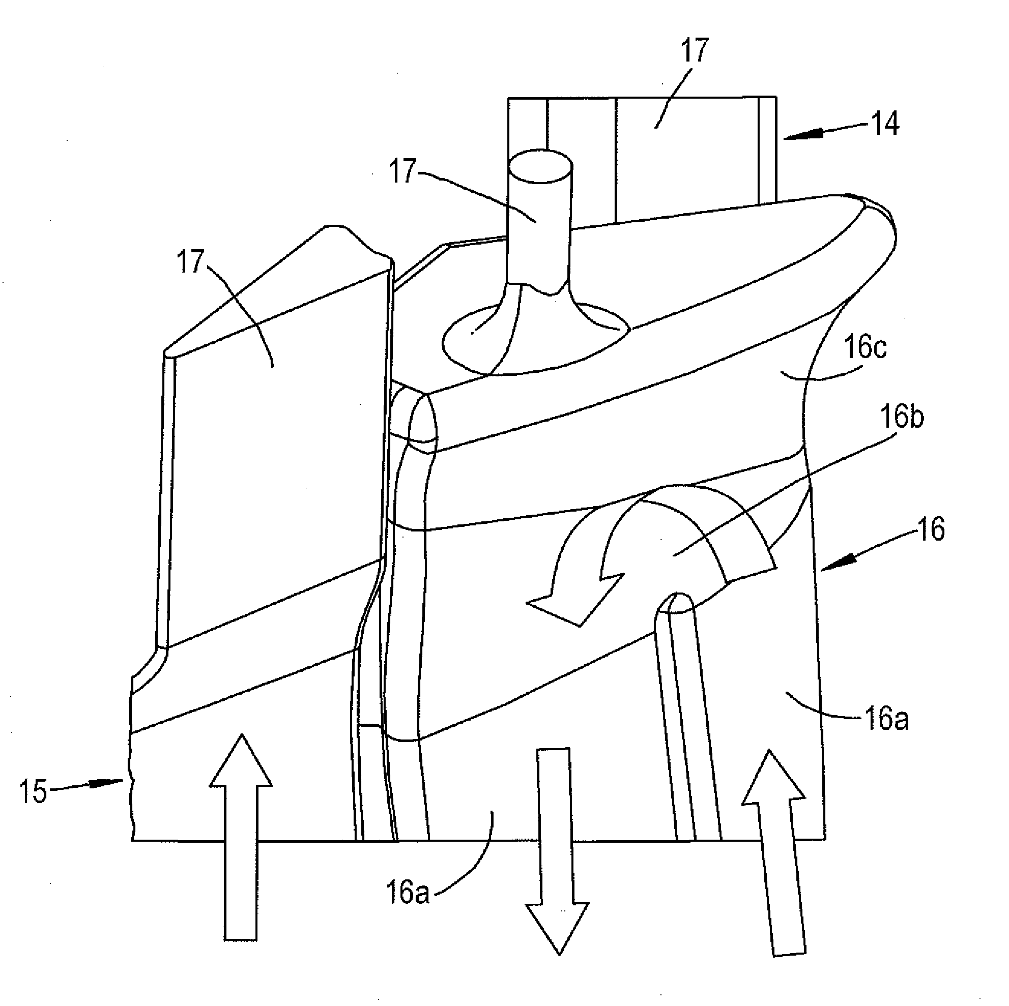
[0048]FIG. 3 shows schematically the radially outer parts of cores for the rotor blade of FIG. 2. The arrows overl...


PUM

PropertyMeasurementUnit
temperaturesaaaaaaaaaa

Abstract

A gas turbine engine rotor blade has an airfoil portion containing one or more internal conduits. Each conduit extends to an end of the airfoil portion. The blade has a shroud at the end of the airfoil portion for sealing the blade to a facing stationary engine portion. There is a fillet portion which joins the end to the shroud. The fillet portion eases the transition from the outer surface of the airfoil portion to the outer surface of the shroud and has a cavity which extends from each conduit and expands laterally relative thereto. The area of the cavity on a cross-section through the fillet portion perpendicular to the radial direction of the engine and at an expanding part of the cavity is greater than the area of the conduit, or the combined areas of the conduits, on a parallel cross-section at the end of the airfoil portion.

Description

CROSS REFERENCE TO RELATED APPLICATION[0001]This application is entitled to the benefit of British Patent Application No. GB 0901129.7, filed on Jan. 26, 2009.FIELD OF THE INVENTION[0002]The present invention relates to a rotor blade for a gas turbine engine, and particularly a rotor blade having an airfoil portion which contains one or more internal conduits for the transport of cooling air therethrough.BACKGROUND OF THE INVENTION[0003]The performance of gas turbine engines, whether measured in terms of efficiency or specific output, is improved by increasing the turbine gas temperature. In modern engines, the high pressure (HP) turbine gas temperatures are hotter than the melting point of the material of the blades and vanes, necessitating internal air cooling of these airfoil components. During its passage through the engine, the mean temperature of the gas stream decreases as power is extracted. Nonetheless, in some engines, the intermediate pressure (IP) and low pressure (LP) t...

Claims


Application Information

Patent Timeline
Patent Type & Authority Applications(United States)
IPC IPC(8): F01D5/18B22D25/00
CPCF01D5/187Y10T29/49339Y10T29/49336F01D5/225F05D2230/31
Inventor TIBBOTT, IAN
Owner ROLLS ROYCE PLC
Why Eureka
Try Eureka