Manufacturing Method of Semiconductor Device

a manufacturing method and semiconductor technology, applied in the direction of semiconductor devices, electrical devices, basic electric elements, etc., can solve the problems of complex viscosity control between the lots of the underfill material, joint may brake, and take considerable time, so as to simplify the manufacturing process, improve product quality, and achieve high reliability

Active Publication Date: 2010-07-29
LINTEC CORP
View PDF19 Cites 89 Cited by
  • Summary
  • Abstract
  • Description
  • Claims
  • Application Information

AI Technical Summary

Benefits of technology

[0020]According to a manufacturing method of a semiconductor device of the present invention, even if voids are produced in an adhesive film used as an underfill material during mounting steps, the voids are removed by applying the static pressure, thereby the semiconductor device having a high reliability can be obtained. That is, the present invention provides the manufacturing method of a semiconductor device capable of continuously performing the mounting process which applies a so-called DBG process and a flip chip bonding method; and can contribute to simplify the manufacturing process and to improve the product quality.

Problems solved by technology

However, in this method, when exposed to a periodical temperature fluctuation, there is a possibility that the joint may brake due to the difference of a thermal expansion coefficient between the semiconductor chip and the chip mounting substrate.
This causes to take considerable amount of time during the step of filling the underfill material without forming any voids; and viscosity control between the lots of the underfill material is complicated.
Also, the amount of the underfill material to be filled is inconsistent which causes the quality of the product to vary.
When placing the sheet-like underfill material between the chip circuit face and the chip mounting substrate, the underfill material may break since the sheet-like underfill material is stretched due to the bump tips formed on the chip circuit face.
When the underfill material is broken, it may cause the voids in the underfill material.
Also, when adhering the sheet-like underfill material to the circuit face, air bubbles may be taken into the root part of the bumps depending on the form of the bumps thereby causing the voids.
Also, although it depends on the type of the underfill materials, the voids may be formed due to the gas generated from the underfill materials during the curing step of the underfill materials.
If these voids remain within the underfill materials, it may become a starting point of the package crack.
However, there are various package designs of the semiconductor device; further, the form, height and density of the bumps, and the surface form of the chip mounting substrate varies in a wide range, thus it is difficult to optimize the die-bonding condition.
However, even when mounting such chip having the bumps, the above described problem of the voids production cannot be solved.

Method used


Image

  • Manufacturing Method of Semiconductor Device
  • Manufacturing Method of Semiconductor Device
  • Manufacturing Method of Semiconductor Device

Examples


example 1

[0112]The adhesive film having the supporting film in which the release film has been removed were laminated to the bump face of the wafer by a rubber laminate roller (rubber hardness 50) with a laminator (RAD 3510 m / 12, manufactured by Lintec Corporation) under the conditions of laminating speed 3 mm / sec and load 3 MPa. Note that, the temperatures of the laminate roller and the table were 25° C.

[0113]The voids produced in the adhesive film while laminating the adhesive film to the wafer were removed ((IP) step), by introducing the wafer laminated with the adhesive film (the stacked body including the adhesive film) into the heat compression device (autoclave under air atmosphere, manufactured by KURIHARA Manufactory Inc.), then heating for 30 minutes at 50° C. under the static pressure of larger by 0.5 MPa with respect to the ambient pressure. The removal of the voids were visually confirmed and evaluated before and after the static pressure application step. The removal of the voi...

example 2

[0120]As similar to the example 1, the adhesive film was laminated to the bump face of the wafer, then without performing the static pressure step, the energy-ray curable resin of the adhesive film was cured.

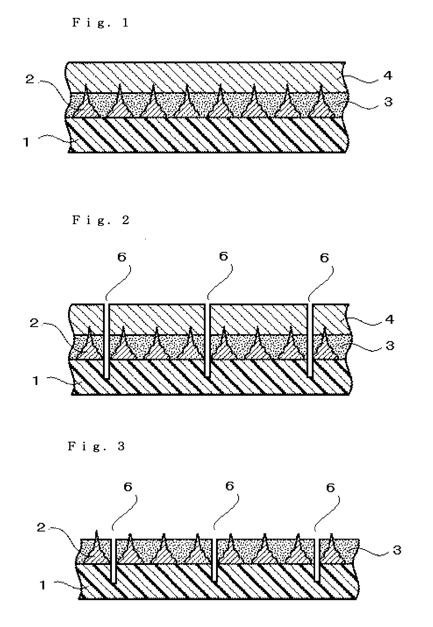
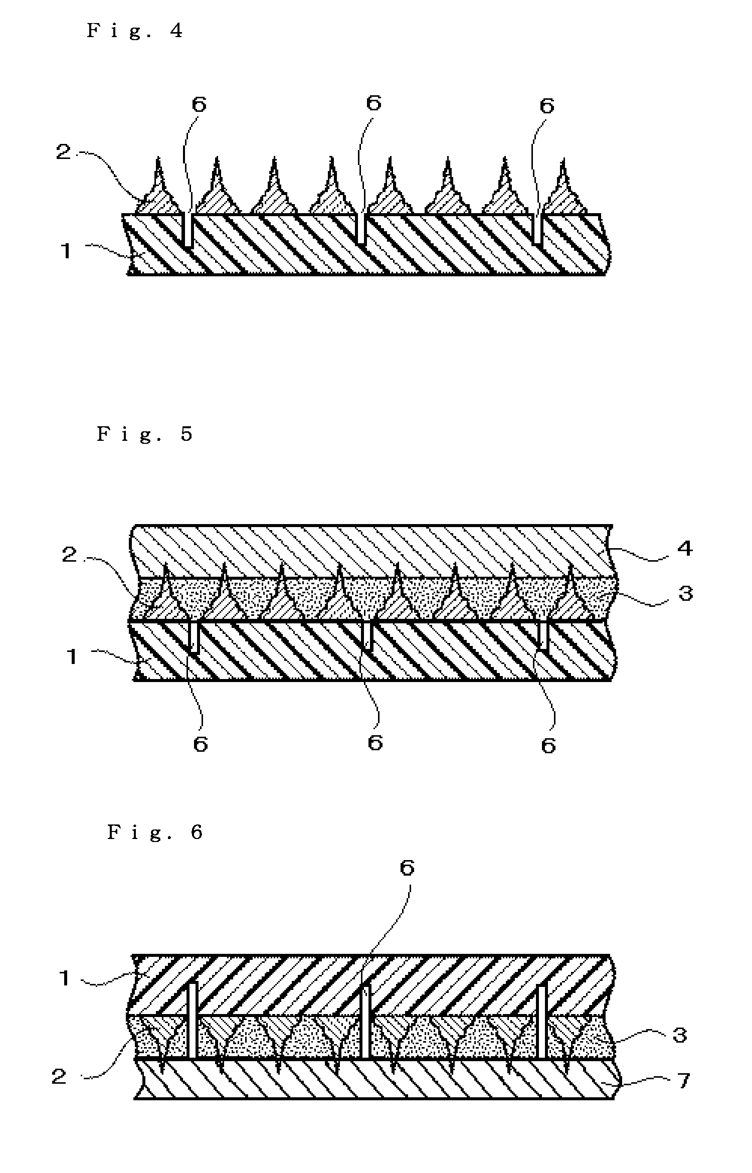
[0121]After removing the supporting film, the grooves along the circuit of the wafer were formed on the stacked body of the adhesive film and the wafer, by cutting from the adhesive film side using the dicer so that the depth of the grooves is 130 μm from the circuit face of the wafer ((FC) step). Next, the surface protective sheet was laminated on the adhesive film side of the wafer. (Hereinabove (S1) step) Then, the opposite side of the circuit face was ground by using the grinder so that the finished thickness is 100 μm; thereby the wafer was divided together with the adhesive film ((S2) step).

[0122]Next, as similar to Example 1, the group of chips having the adhesive film was transferred to the ultraviolet curable adhesive sheet. After that, the chip having the adhesive film...

example 3

[0126]As similar to Example 2, the chip having the adhesive film was obtained, similarly picked up, and die-bonded to the chip via the adhesive film ((S1) to (S4) and (FC) steps).

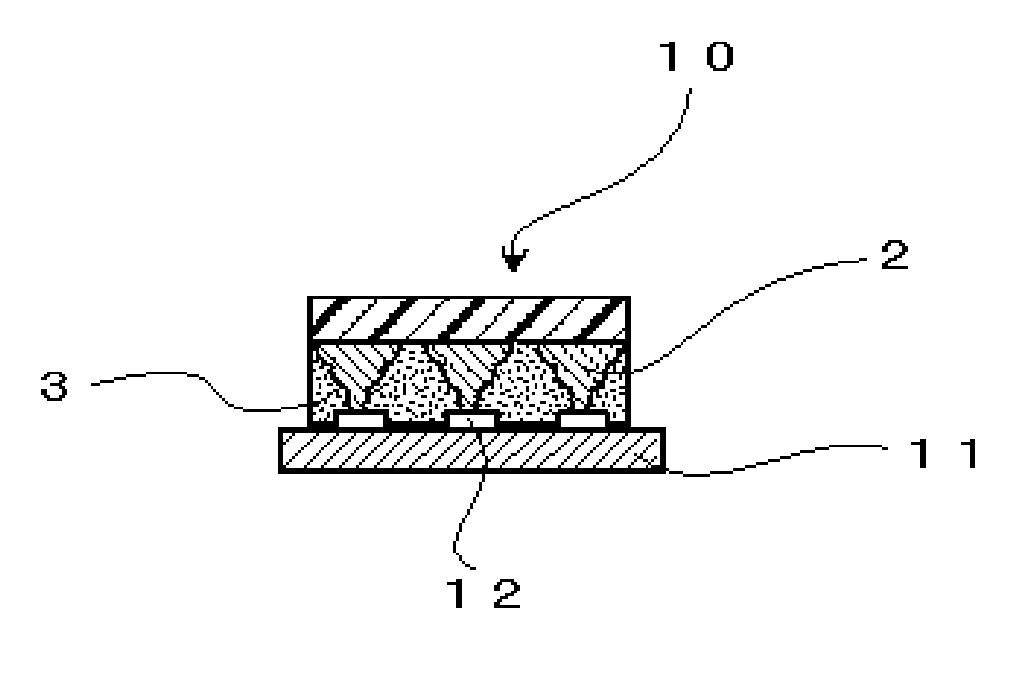
[0127]The die-bonded chip mounting substrate (the stacked body including the adhesive film) was introduced into the heat compression device (autoclave manufactured by KURIHARA Manufactory Inc.), and heated under static pressure of larger by 0.5 MPa with respect to the ambient pressure at 120° C. for 60 minutes and followed by heating at 140° C. for 60 minutes in a stepwise fashion to remove the voids and to cure the adhesive film ((IP) and (S5) steps). The removal of the voids was confirmed by applying the static pressure compared to before applying the static pressure. Also, the conductivity and the insulation of the obtained semiconductor device were good.


PUM


Abstract

The present invention has been achieved reflecting such situation, and its object is to provide a manufacturing method of a semiconductor device capable of continuously performing the mounting process which applies a so-called DBG process and a flip chip bonding method, and can contribute to simplify the manufacturing process and to improve the reliability with no void in the product. The manufacturing method of a semiconductor device according to the present invention comprises:laminating a surface protective sheet to a circuit surface side of a wafer formed with grooves which divide each circuit wherein an adhesive film is adhered on the circuit surface of the wafer;reducing the thickness of the wafer and finally dividing the wafer into individual chips by grinding a back face of the wafer;picking up individual chips together with the adhesive film;die-bonding said individual chip to predetermined position of a chip mounting substrate via said adhesive film;fixing the chip to the chip mounting substrate by heating the die-bonded chip having the adhesive film; andapplying a static pressure larger than an ambient pressure by 0.05 MPa or more to a stacked body including the adhesive film one or more times, at any point between adhering the wafer to the adhesive film and fixing the chip to the chip mounting substrate.

Description

TECHNICAL FIELD[0001]The present invention relates to a manufacturing method of a semiconductor device. Further specifically, the present invention relates to a manufacturing method of a semiconductor device capable to continuously perform the mounting process which utilize a Dicing Before Grinding (DBG) process and a flip chip bonding process, and also the present invention relates to a manufacturing method of semiconductor device capable to contribute to simplify the manufacturing process and to improve the product quality.BACKGROUND ART[0002]For mounting multipin LSI packages to prepare MPUs, gate arrays or the like onto printed wiring boards, a flip chip mounting method has hitherto been adopted in which conductive projections (bumps) made of eutectic solder, high-temperature solder, gold or the like are formed on a connection pad part at a circuit surface side of a semiconductor chip (hereinafter referred as a chip or chips) and are confronted with and are brought into contact ...

Claims


Application Information

Patent Timeline
Patent Type & Authority Applications(United States)
IPC IPC(8): H01L21/50
CPCH01L21/304H01L21/563H01L21/6836H01L21/78H01L24/27H01L24/83H01L24/90H01L2221/68327H01L2221/6834H01L2224/1134H01L2224/131H01L2224/13144H01L2224/13147H01L2224/274H01L2224/27436H01L2224/73203H01L2224/83191H01L2224/838H01L2924/01004H01L2924/01005H01L2924/01015H01L2924/01018H01L2924/01025H01L2924/01027H01L2924/01029H01L2924/01047H01L2924/01073H01L2924/01075H01L2924/01079H01L2924/01082H01L2924/01088H01L2924/01322H01L2224/2919H01L2924/00013H01L2924/01006H01L2924/01019H01L2924/01033H01L2924/014H01L2924/0665H01L24/29H01L2224/16225H01L2224/32225H01L2224/73204H01L2224/73104H01L2224/81191H01L2924/00015H01L2924/00014H01L2224/13099H01L2924/00H01L2924/3512H01L2924/351H01L2224/83208H01L2224/81903H01L2924/00011H01L2224/0401
Inventor MAEDA, JUNTANAKA, KEIKOYAMAZAKI, OSAMU
Owner LINTEC CORP
Why Eureka
Try Eureka