Travel drive apparatus for a working vehicle

a technology for working vehicles and drive apparatuses, which is applied in the direction of propulsion parts, machines/engines, gas pressure propulsion mountings, etc., can solve the problems of reducing reducing the service life of the pump, and reducing the so as to prevent overheating and enhance the reliability and service life of the apparatus.

Active Publication Date: 2010-07-29
NIHON KENKI CO LTD
View PDF5 Cites 39 Cited by
  • Summary
  • Abstract
  • Description
  • Claims
  • Application Information

AI Technical Summary

Benefits of technology

[0014]In view of the above-discussed problem with the prior art, it is an object of the present invention to provide a travel drive apparatus for a working vehicle in which a temperature difference is determined between the temperature of the lubricant oil detected by the temperature sensor before stopping the lubricant pump and a predetermined warning temperature, and a warning is issued when it is determined that this temperature difference is within a predetermined threshold value range, thereby making it possible to prevent overheating and enhance the reliability and service life of the apparatus.
[0017]With the arrangements just described, since the control means constituting a part of the lubricant oil circulation means is configured to control the drive and stop of the electric motor in accordance with the rotational speed of the wheel, the lubricant pump can be started by driving the electric motor when the rotational speed of the wheel (travel speed of the vehicle) is lower than a predetermined determination speed, thereby forcibly circulating the lubricant oil pooled in a wheel mounting case. In consequence, the temperature of the lubricant oil which flows through circulation lines including the wheel mounting case can be lowered by using an oil cooler, and the lubricant oil whose temperature is low can be supplied to the reduction gear mechanism inside the wheel mounting case, thereby making it possible to enhance the lubrication performance and cooling performance.
[0018]On the other hand, in this state, when the rotational speed of the wheel has become faster than the determination speed, the lubricant oil in the wheel mounting case behaves in such a manner as to stick to the entire periphery of the inner wall surface of the wheel mounting case under the influence of the centrifugal force, so that there is a possibility that the action of sucking the lubricant oil by the lubricant pump becomes impossible. Accordingly, in such a case, the control means stops the drive of the lubricant pump by the electric motor and makes it possible to prevent the lubricant pump from assuming an idling state and continuing dry operation.
[0021]By virtue of this configuration, when the operator of the working vehicle has lowered the rotational speed of the wheel (travel speed of the vehicle) to a level equal to or less than the determination speed in accordance with the warning of “overheat” or “excess speed”, it is possible to operate the lubricant pump again by driving the electric motor, thereby making it possible to forcibly circulate the lubricant oil pooled in the wheel mounting case. In consequence, it is possible to lower the temperature of the lubricant oil by using the oil cooler and supply the lubricant oil whose temperature is low to the planetary gear reduction mechanism inside the wheel mounting case, thereby making it possible to enhance the lubrication performance and cooling performance.
[0023]In consequence, when it is determined that the temperature of the lubricant oil is within the range of the aforementioned threshold value despite the fact that the temperature of the lubricant oil is lower than the warning temperature by, for example, 5° C. or thereabouts, it is possible to prevent a warning from being issued immediately by the warning signal output means and prevent an excess burden from being imposed on the operator. In addition, by issuing a warning after the lapse of the predetermined delay time, a timely warning can be provided to the operator.
[0024](4) Further, according to the present invention, the delay time set means is configured to set the delay time to be long when the temperature difference falling within the threshold value is large, and is configured to set the delay time to be short when the temperature difference is small. In consequence, it is possible to set a delay time corresponding to the temperature difference between the temperature of the lubricant oil and the warning temperature. It is possible to issue an overheat warning when the delay time has elapsed, so that the operator can be notified of an overheat warning corresponding to the actual temperature of the lubricant oil.

Problems solved by technology

Accordingly, when the travel speed of the working vehicle is increased to cause the suction port of the suction pipe disposed in the wheel mounting case to become located away from the surface level of the lubricant oil, the action of sucking the lubricant oil by the lubricant pump becomes impossible.
As a result, the lubricant pump assumes an idling state and is driven dry, so that seals, bearings, and the like of the lubricant pump are likely to become worn and damaged at an early period, causing the pump life to become shortened.
However, if the high-speed travel of the working vehicle is continued even after the operator of the working vehicle has stopped the lubricant pump, the temperature of the lubricant oil rises, so that there is a problem in that overheating can undesirably result in some cases.
For this reason, it is, in practice, difficult to provide a temperature sensor, for instance, inside the wheel mounting case to directly detect the temperature of the lubricant oil, since structural restrictions are large.
In this case, however, when the lubricant pump is stopped, it is impossible to detect the temperature of the lubricant oil with the temperature sensor.
In addition, if the travel of the vehicle is continued after the stop of the lubricant pump, there is a problem in that the temperature of the lubricant oil unfavorably rises further.

Method used


Image

  • Travel drive apparatus for a working vehicle
  • Travel drive apparatus for a working vehicle
  • Travel drive apparatus for a working vehicle

Examples


first embodiment

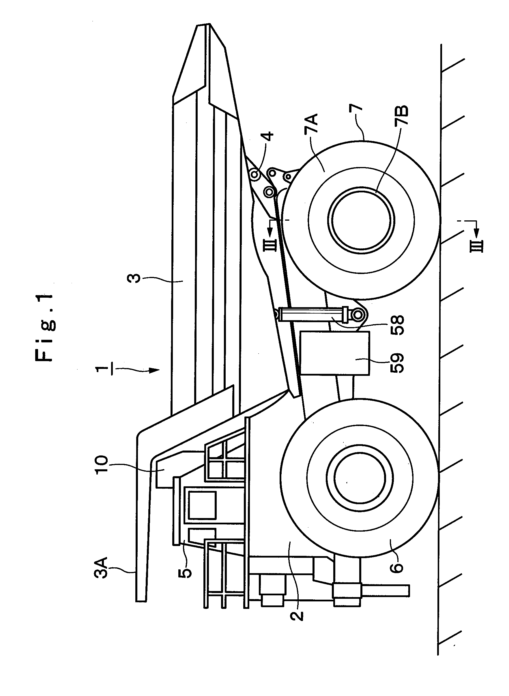
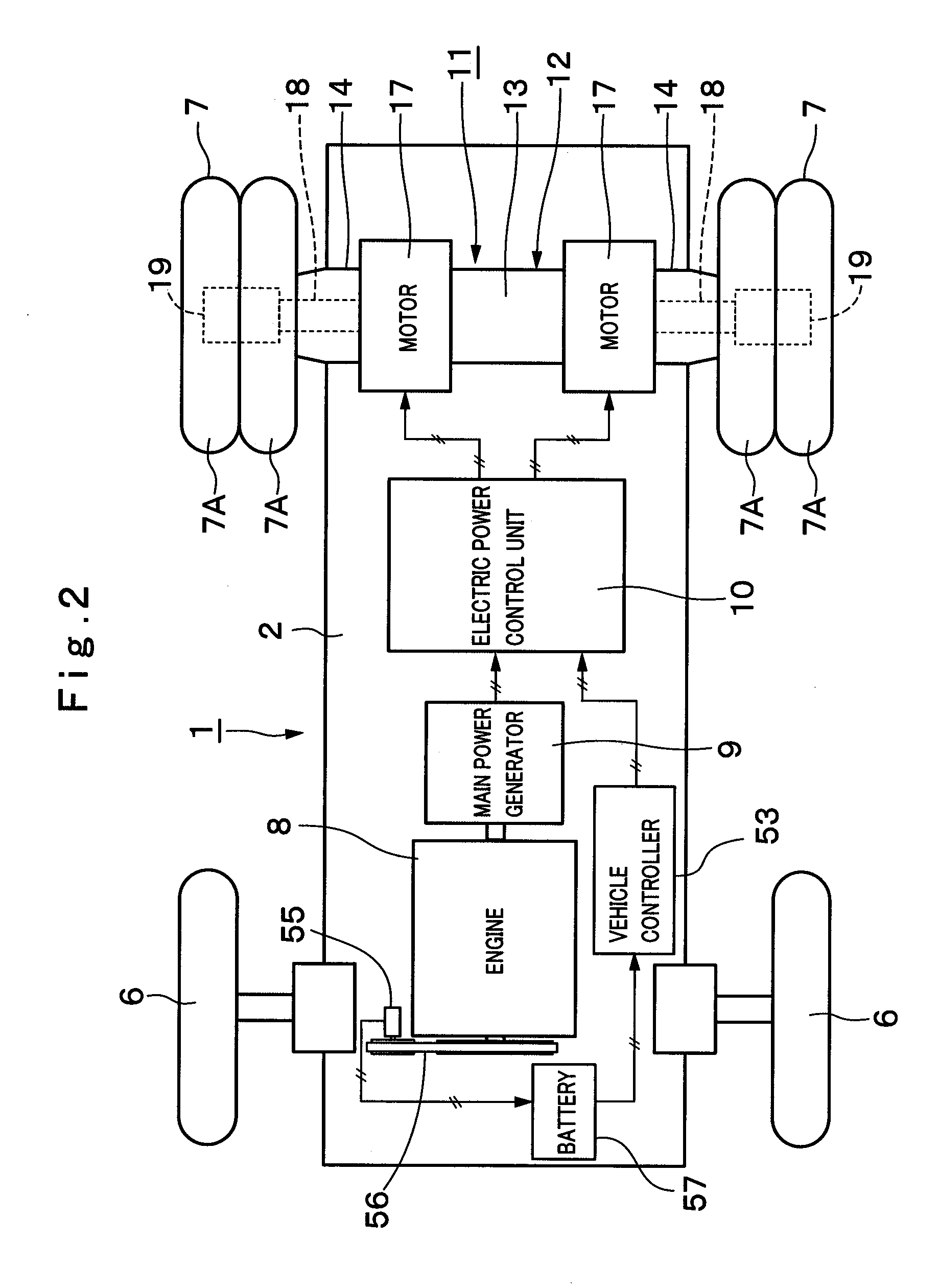
[0043]FIGS. 1 to 7 show the travel drive apparatus for a working vehicle in accordance with the invention.

[0044]In the drawings, indicated at 1 is a dump truck as a typical working vehicle. As shown in FIG. 1, the dump truck 1 is built with a sturdy frame structure, and largely constituted by an automotive vehicle body 2 with below-described front and rear wheels 6 and 7 serving as wheels, and a vessel 3 which is liftably mounted on the vehicle body 2 as a load-carrying platform.

[0045]Further, the vessel 3 is formed as a large-size container whose overall length reaches as much as 10 to 13 meters to load a large volume of heavy load such as crushed stones or other similar objects, and its rear side bottom portion is liftably (tiltably) coupled to a rear end side of the vehicle body 2 by using a pin coupling portion 4. Further, a protector 3A is projected forward from a front top of the vessel 3 in such a way as to cover a cabin 5 from upper side, which will be described hereinafter....

second embodiment

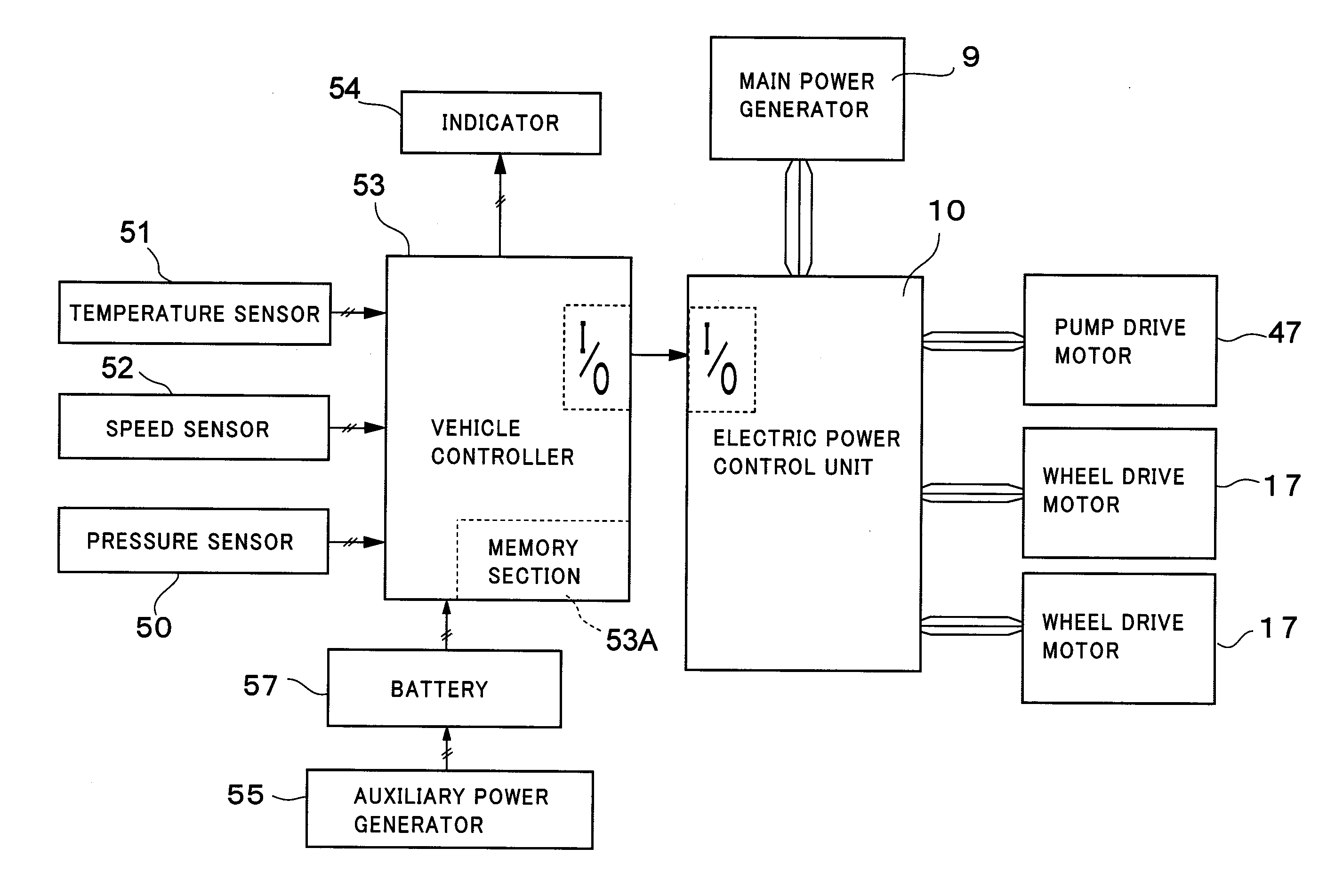
[0135]The characteristic of the second embodiment lies in that a configuration is provided such that when it is determined that the temperature difference ΔT between the temperature T of the lubricant oil G detected by the temperature sensor 51 before stopping the lubricant pump 46 and the warning temperature Toh is within the range of the threshold value α, the “overheat” warning is issued after the lapse of a preset delay time.

[0136]Namely, in the control processing shown in FIG. 8, which is adopted in this embodiment, processing in Step 21 through Step 27 and Step 29 through 31 is carried out in the same way as the processing in Steps 1 to 10 (see FIG. 7) described in the first embodiment. Then, when “YES” is given in the determination processing in Step 31, and the temperature difference ΔT is within the range of the threshold value α, the operation proceeds to a next Step 32 to increment a counter C as “C←C+1”.

[0137]In a next Step 33, a determination is made as to whether or no...

third embodiment

[0145]The characteristic of the third embodiment lies in that a configuration is provided such that when the temperature difference ΔT falling within the range of the threshold value α is relatively large, the delay time until the “overheat” warning is issued is set to be long, whereas when the temperature difference ΔT is relatively small, the delay time is set to be short.

[0146]Namely, in the control processing shown in FIG. 10, which is adopted in this embodiment, processing in Step 41 through Step 44 is carried out in the same way as the above-described processing in Steps 1 to 4 (see FIG. 7) in the foregoing first embodiment. Then, in Step 45, the temperature difference ΔT between the temperature T of the lubricant oil G and the warning temperature Toh based on Step 41 is determined from the aforementioned Formula 1.

[0147]Next, processing in Steps 46 to 48 and Steps 50 and 51 is carried out in the same way as the Steps 5 to 10 (see FIG. 7) described in the foregoing first embod...


PUM


Abstract

When the drive of a lubricant pump (46) is stopped to prevent the lubricant pump (46) from assuming an idling state, a determination is made as to whether or not a temperature difference (ΔT) between the temperature (T) of a lubricant oil detected earlier by a temperature sensor (51) and a warning temperature (Toh) is equal to or lower than a predetermined threshold value (α). When the temperature difference (ΔT) is within the threshold value (α), an “overheat” warning is issued to an operator of a dump truck (1). In consequence, even in a case where a temperature sensor (51) is provided on the output side of the lubricant pump (46) by being located on an outer side of a wheel mounting case (19), planetary gear reduction mechanisms (23), (31) inside the wheel mounting case (19) can be prevented from overheating by warning the operator of the vehicle.

Description

BACKGROUND ART[0001]1. Field of the Invention[0002]The present invention relates to a travel drive apparatus for a working vehicle such as a large-size transportation vehicle and dump truck which is suitably used in transporting crushed stones excavated from a mine or the like.[0003]2. Description of the Prior Art[0004]Generally, large-size transportation vehicles, called dump trucks, have a liftable vessel (a loading platform) on a frame of a vehicle body, and carry heavy objects to be transported like crushed stones in a state in which the objects to be transported are loaded in a large quantity on the vessel.[0005]In this regard, for example, a travel drive apparatus which is adapted to drive a drive wheel of a dump truck is provided with a tubular axle housing which is mounted on a vehicle body, a drive source such as an electric motor or a hydraulic motor which is provided in the axle housing and rotationally drives a rotational shaft, a wheel mounting case rotatably mounted ar...

Claims


Application Information

Patent Timeline
Patent Type & Authority Applications(United States)
IPC IPC(8): G06F19/00F16H57/02F16N29/04B60K6/46B60K7/00B60W10/30B60W20/00F16H1/28F16H57/04
CPCB60B11/06Y10T74/2188F16H57/0435B60K7/0007
Inventor MURAHASHI, TAKAYOSHIMINOSHIMA, TOSHIKAZUKUROSAWA, TAKAO
Owner NIHON KENKI CO LTD
Why Eureka
Try Eureka