In some cases, the developer cannot cleanly partition the database.
Therefore, all nodes must be able to access any part in the parts table; and data collisions or deadlocks will likely occur.
Likewise, if the developer instead partitions the parts table, all transactions (and therefore all nodes) must have access to the customer table, resulting in data collisions.
(In some cases, “dirty reads” can be executed that
read through all types of locks; but
data consistency is not guaranteed as the data may change.)
The applications can resolve the
deadlock by one or both releasing their locks and trying again with random delays, however this is inefficient and costly in the terms of failed operations needing to be resubmitted.
However, when these applications move to a distributed environment using replication to keep multiple database copies in
synchronism, data conflicts such as data collisions (with
asynchronous replication) and distributed deadlocks (with synchronous replication) can occur, as described earlier.
Locking in a bidirectionally-replicated distributed environment such as an active / active
system is somewhat more complicated.
Therefore, the transaction manager does not generally write these locks to the change
queue; and the replication engine will not replicate them to the target
system.
In some cases, it is unnecessary (or perhaps undesirable for performance or application-
concurrency reasons) to replicate read locks.
If the replication engine does not replicate these locks, the ILP is ineffective on the target
system; and data collisions and / or deadlocks may occur.
As a result, data collisions might occur, corrupting the database if they are not detected and resolved.
Both will replicate these changes, causing data collisions and database corruption unless the system can detect and resolve the data collisions.
However, this is not generally the case; and one must find other solutions.
However, it will cause the data object to become locked.
However, upon receiving the replicated null update, the target system will apply the update, though null, to the
target database, consequently locking the target data object.
Some systems cannot guarantee that the target system will execute events within a transaction that affect different tables or partitions in the same order that the source executed them.
For instance,
NonStop systems do not preserve in the audit trail the
order of operations performed on different tables or partitions, as discussed in Section 3.2.7, “
Referential Integrity and
Data Consistency.” For example, in the
Purchase Order example of FIG. 94, in which an application must obtain a read lock on the header row of a
purchase order before it can update any detail lines, there is no guarantee in a
NonStop system that the null update will reach the target before the detail lines.
If the null update follows the changes to the detail lines in the audit trail, the target system will update the detail lines before it acquires a lock on the header row, thus violating the locking protocol.
On the contrary, it increases application-latency time, which in turn extends the time that applications hold the locks.
This increases the likelihood of data collisions in asynchronous systems or distributed deadlocks in synchronous systems.
In some cases, changing read locks to null updates or calling a special API may not be practical because of the expense or risk of modifying an application or even because the
source code may no longer be available.
In addition, some systems do not support intercept technology.
However, the
Consumer's (or alternatively the Collector's) user-exit code must duplicate the business rules for the application's ILP.
If an extended
deadlock occurs, the replication engine will time out and will abort the transaction.
A significant portion of this
delay is the time that it takes for the
source system to materialize the changes to the audit trail.
The materialization time adds not only to lock-
holding time but also to application latency caused by the application having to wait for the replication engine to apply updates across the network.
If it has received the RTC! from AudRtr but is still waiting for the next
tick, this wait becomes an additional
delay.
Thus, the average additional
delay is
As a consequence, there is no application latency
advantage to be gained by using a
Metronome interval that is shorter than the replication channel round-trip time.
Transactions that are being monitored in the failed CPU will be aborted (limitation of the TMF architecture).
For example, lowering application latency may result in poorer WAN performance and higher bandwidth requirements by decreasing the level of message blocking.7. Self-Monitoring
In particular, it will require significant debugging and error
logging capabilities.13.
If there is a transaction coordinator in every CPU, and the applications direct the transaction to the coordinator in their CPU, then those transactions that are aborted would have also been aborted because of the application failure.
A significant drawback to using the buffer acknowledgment scheme is that the target system must apply all data in the block prior to sending the
acknowledgement.
However, if the tag does not match, the collector knows it has sent more data and it needs to wait for another
acknowledgement.
If the target applies and commits all the active transactions, it could corrupt the database with partial data.
If the target aborts all active transactions, it risks removing data for completed transactions on the source.
If the target has responded to the last RTS sent, or if virtual RTS's are being used and all the data for the transaction has been applied and acknowledged, the situation is more complex.
First, the collector is reading the audit trail asynchronously and may be significantly behind when the RTC is issued by the coordinator.
Even worse, one cannot easily determine when all of the disk processes have flushed their changes to the audit trail—they start to flush on the same
signal that the coordinator uses to generate the RTC token.
Solving the problem involves tradeoffs between application latency and performance.
The above two algorithms are not deterministic—there is a chance that portions of a transaction may be delayed and written after the response to the RTC is issued if a disk process is sufficiently delayed in flushing its log.
The
metronome process offers a guaranteed completion, but at performance penalty.
Using the
commit record for the update guarantees that all of the disks will have been flushed, but, it may add some application latency: the time between the last
record flushed to the audit trail and the
commit record being written.
That will further increase application latency however.
This increases application latency, since RTS's that occur within the band are being forced to be delayed for a full
tick.
Replication can be configured to
commit or abort those transactions—however, because multiple RTC requests may be sent for a single transaction, the
router typically cannot be sure if it has received all of the I / Os for a transaction even if it has received the RTC request.
The application will be blocked until it responds and will not be able to do any I / Os or commits.
However, if the time to register a transaction with TMF is close to the round trip time of an IPC, it will not be worth implementing the second option.
The current method of scaling replication, which is based upon table / partitions, does not ensure transaction consistency.
Customers want database integrity with a consistent view of the replicated data—something that is not possible when multiple consumers using
multiple target transactions process a single source transaction.
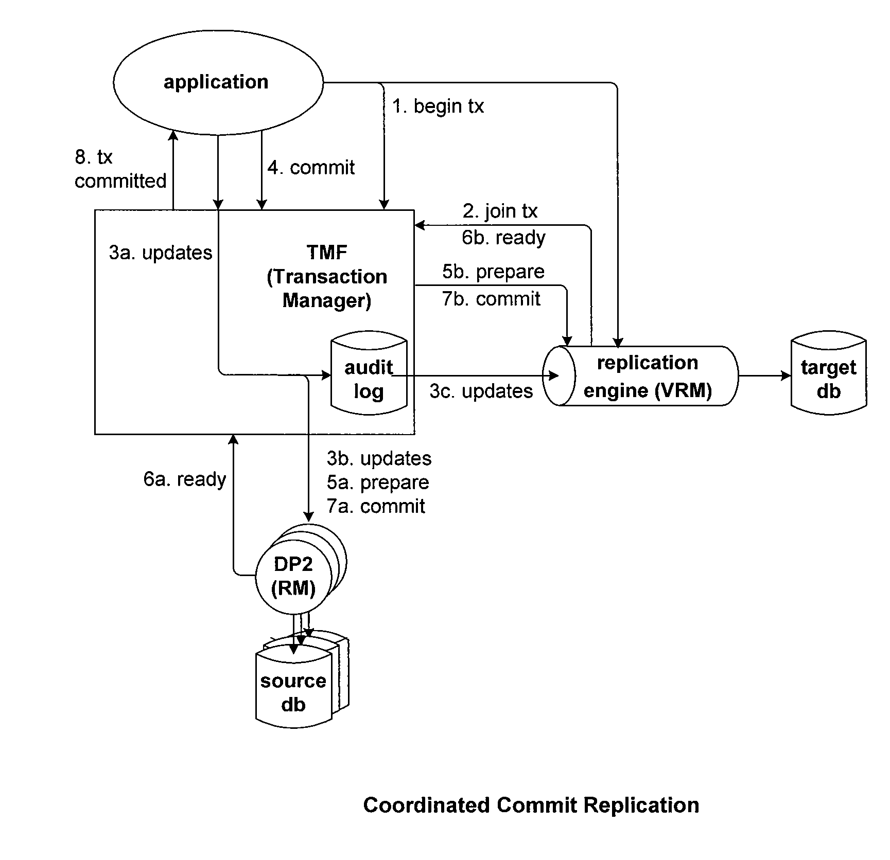
Transactional interactions become more important since a source transaction cannot be committed until the data has been replicated—transactions can not be allowed to delay other transactions.
This solution has a number of performance problems, including:1) Only one transaction to the
consumer can be outstanding at given time, or some significant overhead needs to be added to cancel queued outstanding requests.2) Buffering will be reduced—more IPCs will be required.
It does increase the application latency of the transaction since the I / O operations are postponed and done in a batch.
Transaction based routing does not work well for asynchronously replicated transactions since the changes and commits can be applied out of order.
The same problem can occur if the first transaction was committed asynchronously and the second synchronously.
Note that this problem only occurs if the first transaction is asynchronous: if the first transaction is synchronous, the data will be applied at the replication destination in the correct order.
This is an application bug, but can occur either if the intercept
library was not bound into one or more processes or if the application is using the callable
library and misses a call to register the transaction.2) The
Metronome process is not used, and one disk process is significantly delayed in updating the audit trail, allowing some data to be written to the destination after the coordinator has voted to commit,3) While
processing the backlog of
transaction data during a restart.
However, the two cases differ slightly in how they will be handled.Case 1: In the first case (application problem), an error is logged at commit time.
T2's response to the RTC, however, is delayed because T1's commit has not completed.
The pessimistic approach is easier to implement but may have a significant
impact on both latency and
throughput.
The pessimistic approach significantly reduces the parallelism possible when there are a large number of asynchronous transactions replicated.
However, if there are only a few transactions replicated asynchronously it significantly reduces the complexity of
processing.
Running multiple routers in the same replication environment poses additional problems.
In this configuration, each
router only sees a subset of transactions and may not be able to tell if a previous transaction has been committed or not.
Of course, the simplest approach is not to allow transactions with post-RTC data.
As noted above, this type of processing is problematical if replication is configured to be synchronous with routing to the
consumer based upon source transaction.
However, by registering all transactions with a flag, the replication subsystem can identify transactions that were never registered, identifying potential application bugs.
The current Shadowbase architecture does not support transactional consistency, where for each source transaction replicated, there is one and only one target transaction except in simple, single threaded architectures.
This is called transaction fanout, and has several disadvantages:1) In a high volume environment, TMF may need to be reconfigured on the Target system to support more simultaneous active transactions.2) If one of the target transactions fail, it is difficult to properly backout the other target side transactions, resulting an inconsistent database.
Moreover, the number of transactions the
router can have active simultaneously is limited.
When it reaches the limit, it will need to suspend and activate transactions, adding additional overhead.
Issuing a RTS from the application may significantly increase the application latency for the transaction, as it adds at least a round trip to the target system to the latency.
It also does not eliminate deadlocks when used to replicate locks in an ILP.
However, Shadowbase does not presently replicate lock-only operations.
In short, it is difficult with a cursory inspection to determine whether an application is using the intercept
library or not.
The design of the configuration options for a
complex system is frequently a tradeoff between flexibility and complexity.


