Hybrid valve for internal combustion engines

a hybrid valve and internal combustion engine technology, applied in the direction of engines, machines/engines, mechanical apparatus, etc., can solve the problems of reducing the overall performance and efficiency of the engine, affecting the performance of the engine, so as to achieve the effect of increasing overall performance and efficiency

Inactive Publication Date: 2010-08-05
HUFF REGGIE DWAYNE
View PDF12 Cites 9 Cited by
  • Summary
  • Abstract
  • Description
  • Claims
  • Application Information

AI Technical Summary

Benefits of technology

[0020]The independent control and displacement of the ring seal(s) allows each engine cylinder to time its actuation with its own independent flow demand and timing, which varies throughout a wide spectrum of speed versus load conditions. This allows for increases in overall performance and efficiency of single to multi-cylinder internal combustion engines over a broad range of conditions and applications.

Problems solved by technology

Due to the mechanical limitations of this traditional method, lengthy initial opening and final closing events are necessary to dampen the valve's opening and closing action.
This condition has a particularly negative effect on the low to mid-speed performance, fuel economy, and emissions of typical internal combustion engines.
These mechanical limitations also limit the phase timing, lift, duration, rate of lift, and all timing dimensions relative to associated (co-joined) cylinders to one single static timing for all valves relative to all cylinders at all times and in all conditions relative to crankshaft angle.
This forces the engine designer to accept compromises that have a negative effect on engine performance, fuel economy, and emissions, at virtually all speed and load settings.

Method used


Image

  • Hybrid valve for internal combustion engines
  • Hybrid valve for internal combustion engines
  • Hybrid valve for internal combustion engines

Examples


Embodiment Construction

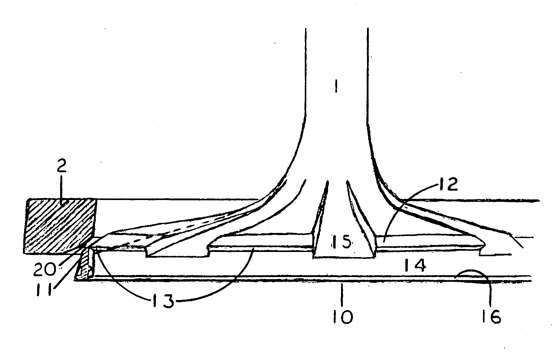
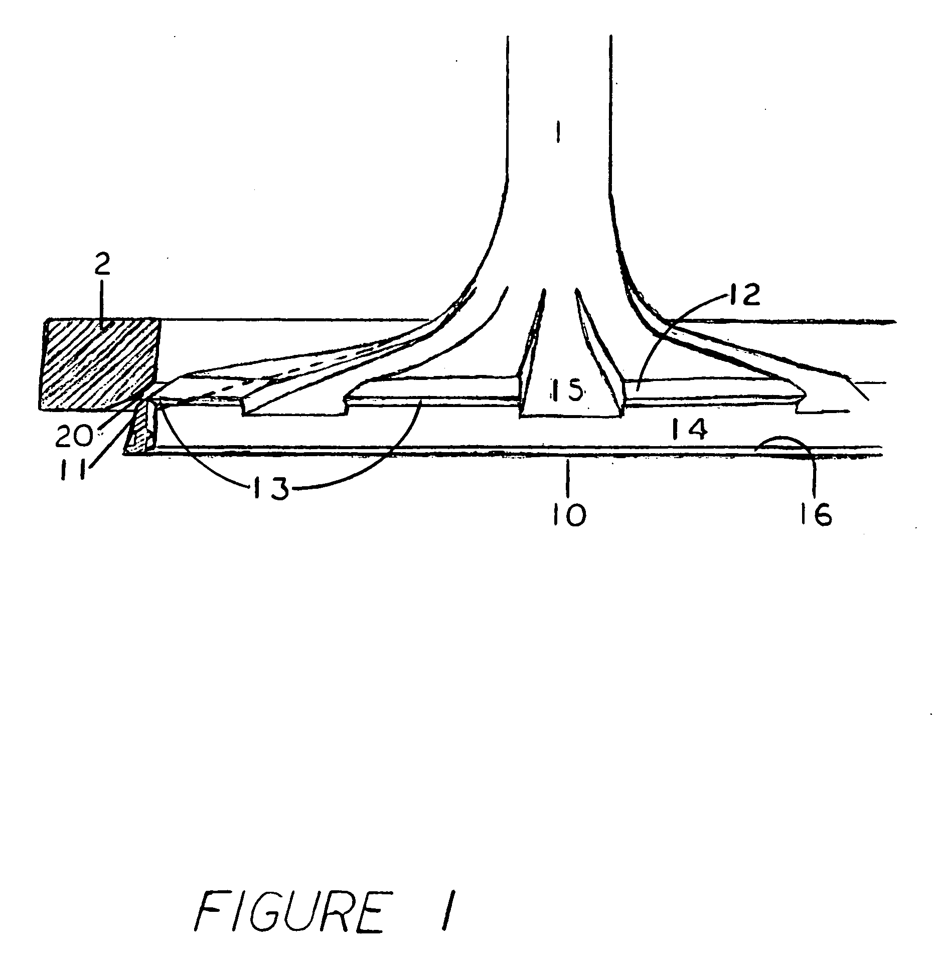
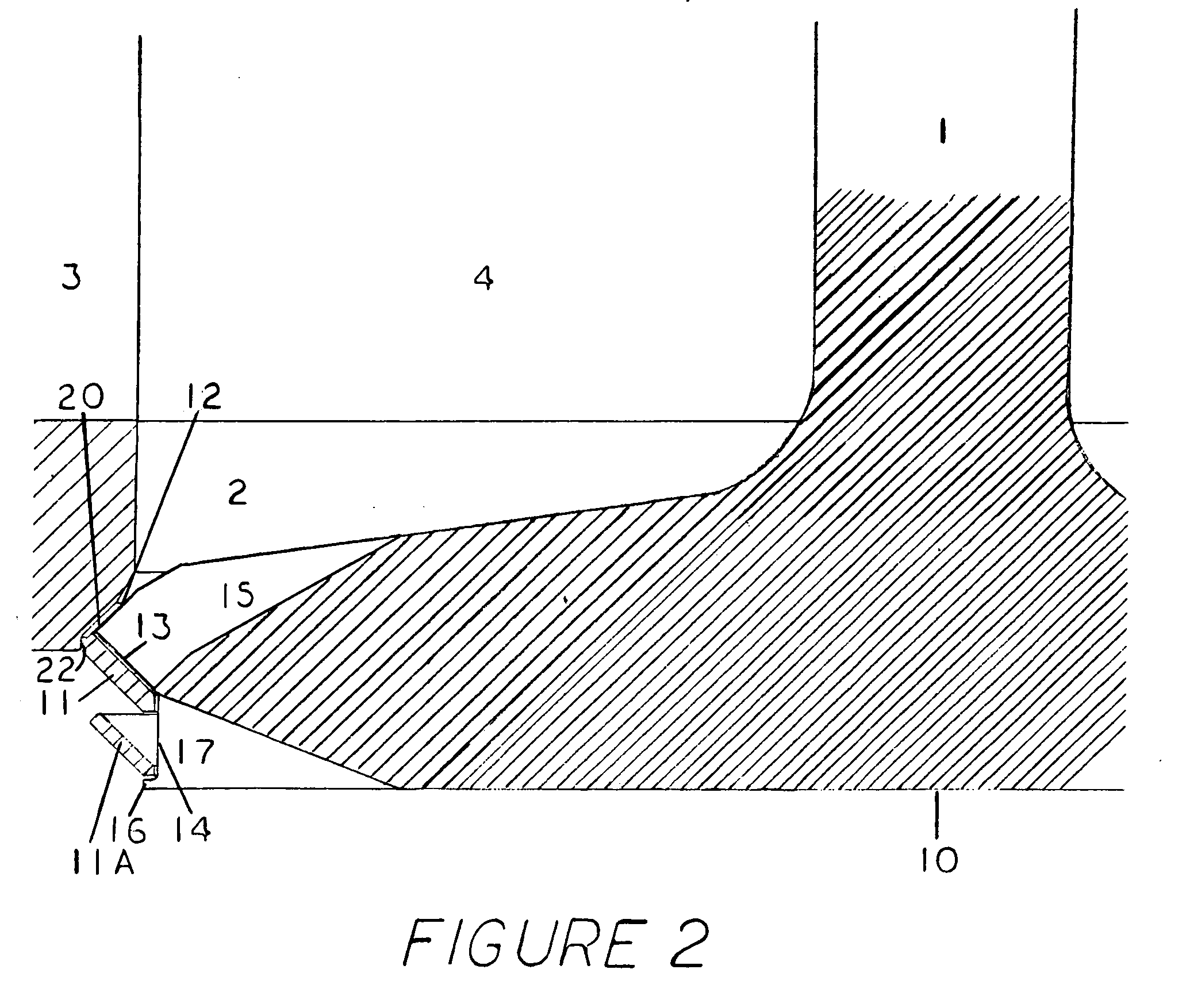
[0029]As illustrated by FIGS. 1, 2, 5&6, the intake valve, #1, is arranged within a typical internal combustion engine to releasably seal an intake port, FIG. 6-#4. The intake valve includes a valve base (head), FIG. 1, 2, 5&6-#10, which, in one preferred embodiment, is specially formed to accept an auxiliary annular ring seal, #11, around the outer periphery of the intake valve base, FIG. 1, 2, 5&6-#10.

[0030]As depicted in FIGS. 1 & 2 the intake valve base #10, is designed with jet flow passage ways #15, evenly spaced around the outer periphery of the main valve head #10, which creates an interrupted main base seat #12. An annular ring seal #11, is configured so as to allow its controlled linear coaxial displacement in line with the main intake valve stem, #1, to a predetermined limit by means of a guide margin FIG. 1-#14. The annular ring seal #11, is configured with an angular seating surface FIG. 4-#30, designed to engage and mate with an inverted interrupted seat #13, and an an...


PUM


Abstract

A next generation hybrid valve concept for enhanced induction cycle function for internal combustion engines. Said hybrid valve effectively combining automatic pressure activated check valve function with traditional poppet valve function to create an effective low cost self regulating variable valve timing (VVT) system. Said hybrid valve consisting of a free floating annular ring seal which is affixed concentrically around a modified poppet valve seat or within an engine head seat insert configured with releasably sealable jet flow passage ways.
The concept can provide an effective range of late opening and early closing times to control reversion as well as a very broad range of early opening and late closing times. In addition, the actuation of the free floating ring seal is variable, automatic and controlled and timed very precisely by cycle exchange functions allowing for effective variable valve function in four (4) dimensions within single cylinder engines and five (5) dimensions within multi-cylinder engines.

Description

BACKGROUND[0001]The invention here disclosed relates primarily to a reciprocating intake valve and / or engine head seat insert controlling the movement of air or air / fuel mixture into the combustion chamber (cylinder) of internal combustion engines.[0002]In typical internal combustion engines the intake valves and the engine head seat inserts are of a single piece construction and are incapable of varying their opening and / or closing events independent of typical valve control mechanisms.[0003]Since the efficiency and timing of this valve arrangement is a major factor in the performance of the entire engine, there have been many attempts at improving the mechanical motion of valves to maximize the flow dimension (volume) of the typical valve and port arrangement. Further, since the timing of these valve arrangements is an important factor in the performance of internal combustion engines, many attempts to vary the timing of the displacement of intake and, to a much lesser extent, exh...

Claims


Application Information

Patent Timeline
Patent Type & Authority Applications(United States)
IPC IPC(8): F16K1/00
CPCF01L3/00F01L3/06Y02T10/146F01L3/22F01L3/20Y02T10/12
Inventor HUFF, REGGIE DWAYNE
Owner HUFF REGGIE DWAYNE
Why Eureka
Try Eureka