Internal combustion engines
- Summary
- Abstract
- Description
- Claims
- Application Information
AI Technical Summary
Benefits of technology
Problems solved by technology
Method used
Image
Examples
Embodiment Construction
[0039]The following is a description of the preferred embodiment, but many variations are possible within the scope of the invention.
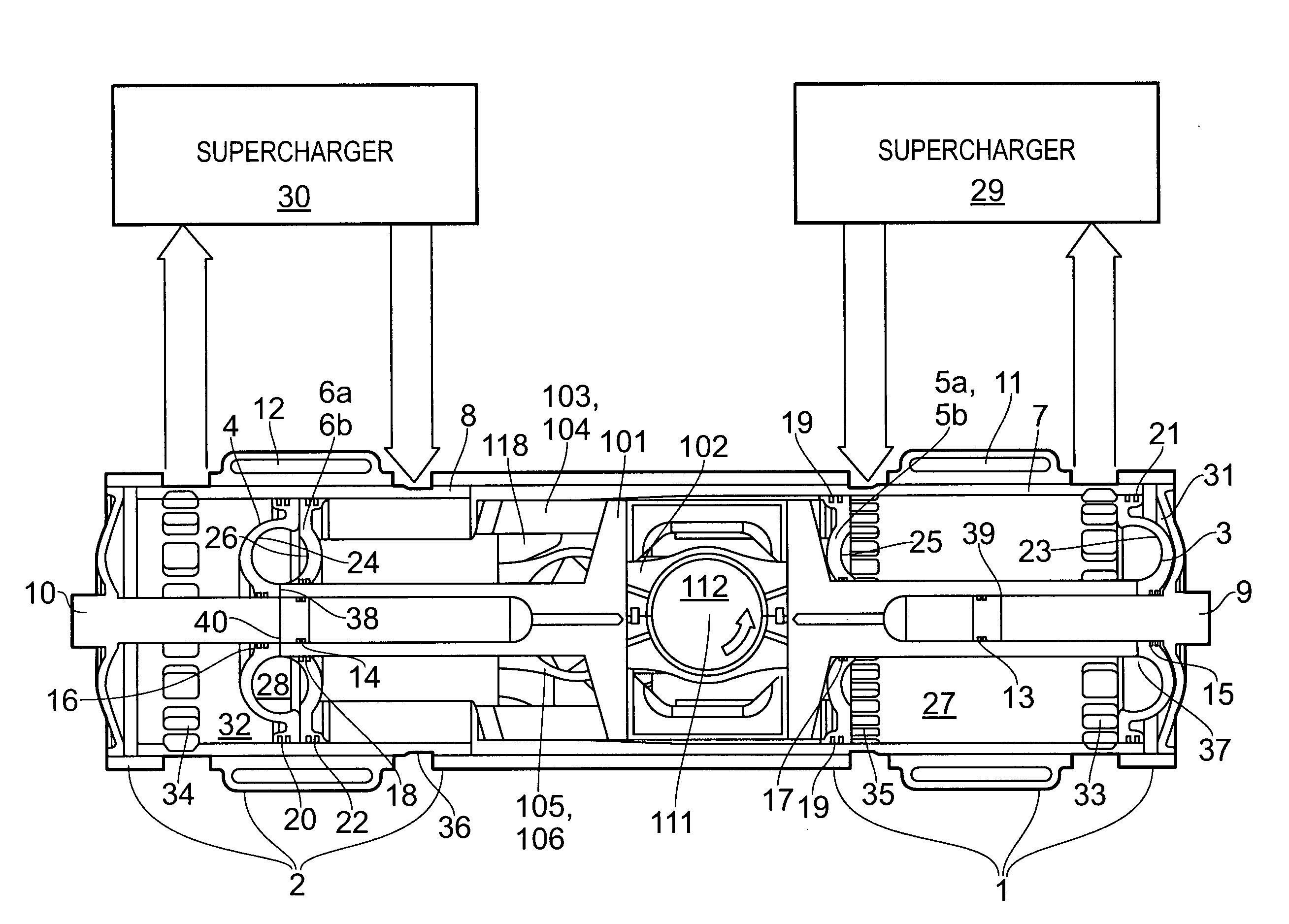
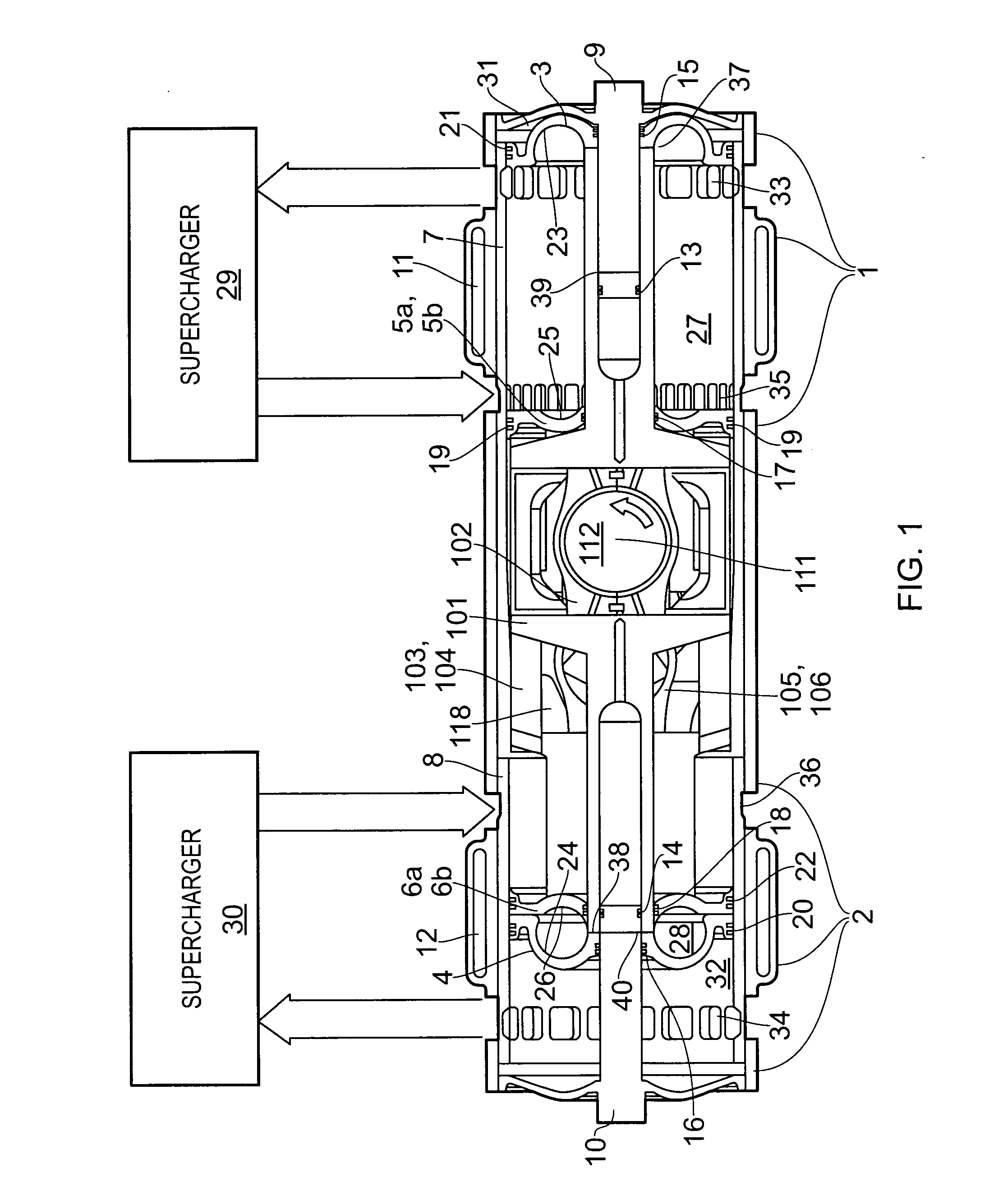
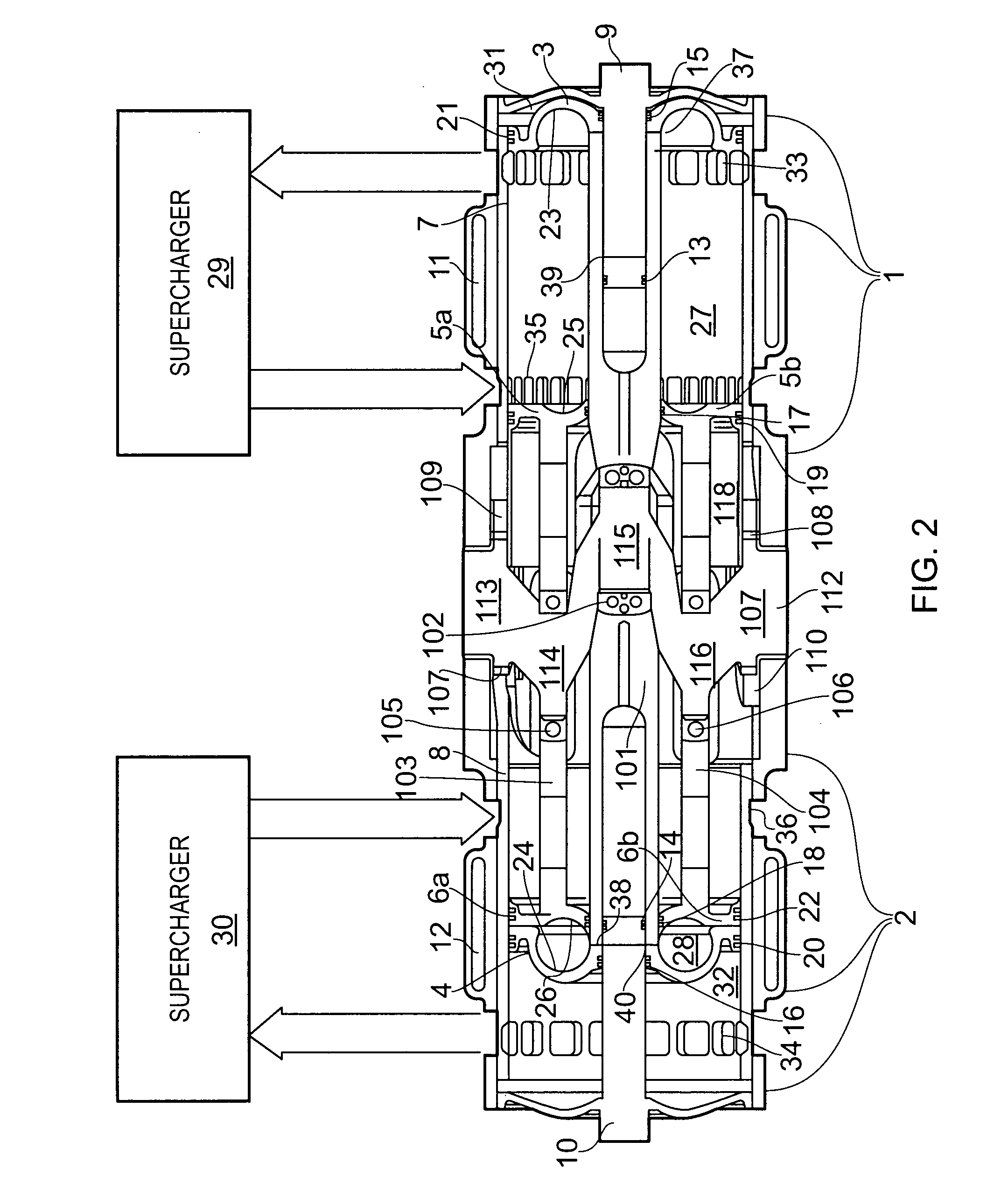
[0040]As illustrated in FIGS. 1 and 2, the engine configuration of the present invention comprises a right cylinder 7, a left cylinder 8 and a single central crankshaft 112 located between the cylinders (for clarity, most of the supporting structure of the engine, apart from 1 and 2 has been omitted from FIGS. 1 and 2).
[0041]The right cylinder 7 has an outer piston (PRO) 3 and an inner piston (PRO) 5 with combustion faces 23 and 25 respectively, the two pistons forming a combustion chamber 27 between them. The left cylinder 8 similarly has an outer piston 4 (PLO) and an inner piston (PLI) 6, with combustion faces 24 and 26 and combustion chamber 28. The two outer pistons 3 and 4 are rigidly connected together by the scotch yoke 101. The two upper, inner piston halves 5a and 6a are rigidly connected together by the upper scotch yoke 103 and the two lowe...
PUM
 Abstract
Description
Claims
Application Information
 - R&D
- Intellectual Property
- Life Sciences
- Materials
- Tech Scout
- Unparalleled Data Quality
- Higher Quality Content
- 60% Fewer Hallucinations
Browse by: Latest US Patents, China's latest patents, Technical Efficacy Thesaurus, Application Domain, Technology Topic, Popular Technical Reports.
© 2025 PatSnap. All rights reserved.Legal|Privacy policy|Modern Slavery Act Transparency Statement|Sitemap|About US| Contact US: help@patsnap.com


