Control device for internal combustion engine and control method for internal combustion engine

a control device and internal combustion engine technology, applied in the direction of machines/engines, combustion air/fuel air treatment, output power, etc., can solve the problems of difficult to appropriately control the flow rate of gas, degrade the internal combustion engine, and degrade the engine oil, so as to reduce the number of operating cylinders

Active Publication Date: 2010-08-05
TOYOTA JIDOSHA KK
View PDF10 Cites 38 Cited by
  • Summary
  • Abstract
  • Description
  • Claims
  • Application Information

AI Technical Summary

Benefits of technology

[0016]With the above configuration, in the internal combustion engine with the cylinder cut-off mechanism or the variable valve mechanism, the opening degree of the flow rate control valve, corresponding to the target value of the flow rate of gas returned to the blow-by gas passage, is variably set on the basis of an intake pressure in the intake passage. Therefore, in the internal combustion engine of which the relationship between the engine load and the intake pressure is not uniquely defined because any one of the above mechanisms is provided, when the flow rate control valve with an actuator is provided to adjust the flow rate of blow-by gas, it is possible to appropriately control the flow rate of blow-by gas.
[0017]A second aspect of the invention provides a control device for an internal combustion engine that includes a blow-by gas passage that returns blow-by gas, flowing from a combustion chamber to a crank chamber, to an intake passage; a flow rate control valve that adjusts a flow rate of gas returned to the blow-by gas passage; an actuator that adjusts an opening degree of the flow rate control valve so that the flow rate of gas becomes a target value; and a cylinder cut-off mechanism that reduces the number of operating cylinders. The control

Problems solved by technology

The blow-by gas leaking into the crank chamber may degrade engine oil and, by extension, degrade the internal combustion engine.
Thus, in the internal combustion engine with any one of the above mechanisms, when the above negative pressure flow rate control valve is used, it may be difficult to appropriately control the flow rate of gas.
For example, as the flow rate of gas excessively increases, oil component contained in blow-by gas also excessively returns to the intake passage, so there is a concern that t

Method used


Image

  • Control device for internal combustion engine and control method for internal combustion engine
  • Control device for internal combustion engine and control method for internal combustion engine
  • Control device for internal combustion engine and control method for internal combustion engine

Examples


first embodiment

[0036]Hereinafter, a control device for an internal combustion engine according to the invention will be described with reference to FIG. 1 to FIG. 4.

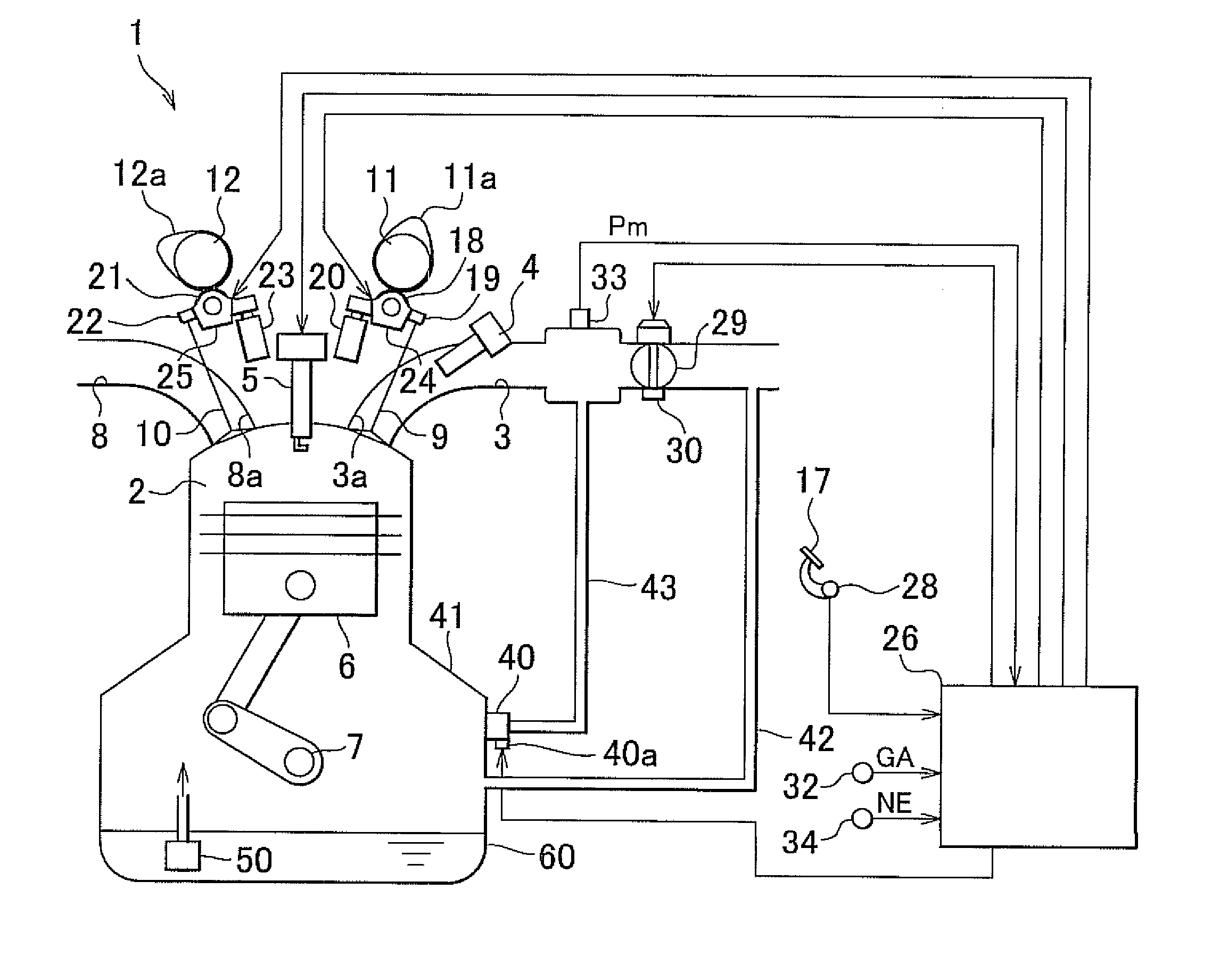
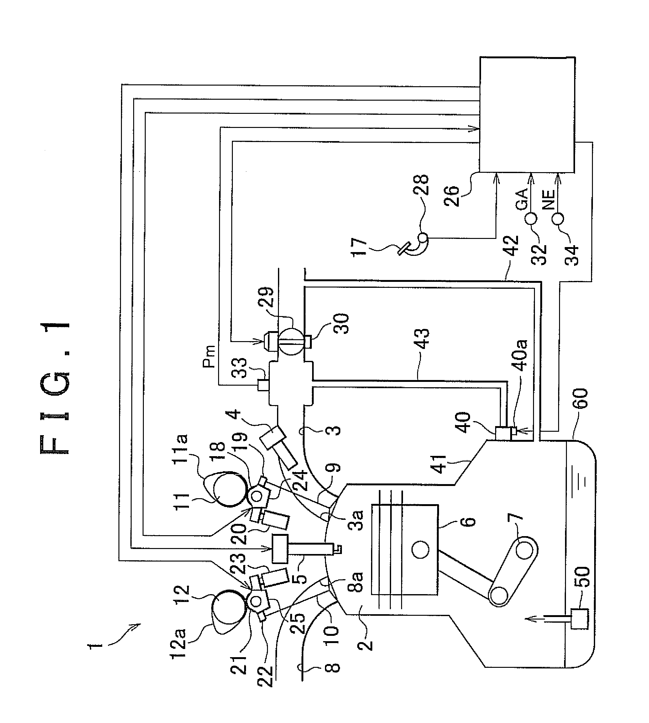
[0037]An engine 1 shown in FIG. 1 is a multi-cylinder internal combustion engine having a plurality of cylinders. By adjusting the opening degree of a throttle valve 29 provided in an intake passage 3 of the engine 1 on the basis of an amount by which an accelerator pedal 17 is depressed (accelerator operation amount), or the like, air of an amount corresponding to the opening degree of the throttle valve 29 is supplied to a combustion chamber 2 of each cylinder via the intake passage 3. In addition, fuel of an amount corresponding to the intake air amount of the engine 1 is injected and supplied from a fuel injection valve 4 to the intake passage 3 of the engine 1. As a result, an air-fuel mixture formed of air and fuel fills the combustion chamber 2 of each cylinder in the engine 1. As the air-fuel mixture is ignited by an ignition p...

second embodiment

[0067]Next, a control device for an internal combustion engine according to the invention will be described with reference to FIG. 5.

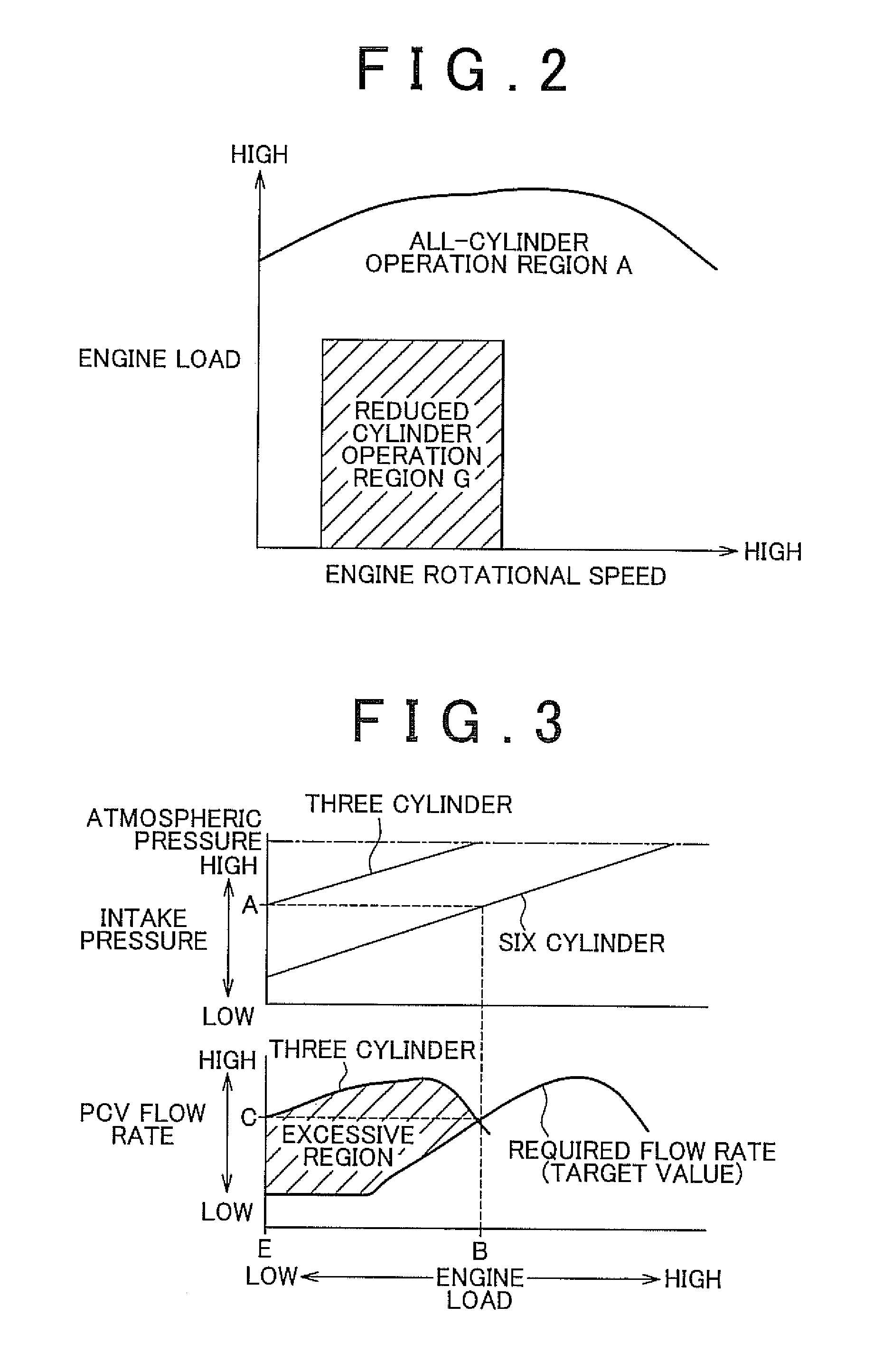
[0068]As described above, in the engine 1 with the cylinder cut-off mechanism, the intake pressure Pm in the intake passage 3 varies on the basis of the number of operating cylinders. Then, in the first embodiment, the intake pressure Pm is detected, and then the opening degree V of the PCV valve 40, corresponding to the required flow rate DE, is variably set on the basis of the detected intake pressure Pm.

[0069]On the other hand, in the second embodiment, in the engine 1 with the cylinder cut-off mechanism, the opening degree V of the PCV valve 40, corresponding to the required flow rate DE, is variably set on the basis of the number of operating cylinders. Then, part of the opening degree setting process in the second embodiment differs from that of the first embodiment, and the intake pressure sensor 33 is omitted in the second embodiment. Then, her...

third embodiment

[0076]Next, a control device for an internal combustion engine according to the invention will be described with reference to FIG. 6 to FIG. 9.

[0077]The third embodiment differs from the first embodiment in that a variable valve mechanism that varies the valve characteristic of each intake valve 9 is provided instead of the cylinder cut-off mechanism, the intake pressure sensor 33 is omitted and part of the opening degree setting process for the PCV valve 40 is changed. Then, hereinafter, the control device according to the third embodiment will be described focusing on the above difference.

[0078]FIG. 6 shows the configuration of the engine 1 according to the third embodiment. As shown in FIG. 6, the engine 1 includes a variable valve lift mechanism 14 as the variable valve mechanism that varies the valve characteristic of each intake valve 9. The variable valve lift mechanism 14 is provided between the intake camshaft 11 and each rocker arm 19, and is driven by an electric motor 15...


PUM


Abstract

An engine includes: a valve stop mechanism that varies the number of operating cylinders as a cylinder cut-off mechanism; and a blow-by gas recirculation system that has a blow-by gas passage that returns blow-by gas, flowing from a combustion chamber to a crankcase, to an intake passage and a PCV valve that is equipped with an electric motor and that adjusts the flow rate of gas returned to the blow-by gas passage. A control device variably sets the opening degree, corresponding to a target value of the flow rate of gas, of the PCV valve on the basis of an intake pressure in an intake passage to adjust the opening degree of the PCV valve so that the flow rate of gas becomes the target value.

Description

INCORPORATION BY REFERENCE[0001]The disclosure of Japanese Patent Application No. 2009-024166 filed on Feb. 4, 2009 including the specification, drawings and abstract is incorporated herein by reference in its entirety.BACKGROUND OF THE INVENTION[0002]1. Field of the Invention[0003]The invention relates to a control device for an internal combustion engine and a control method for an internal combustion engine.[0004]2. Description of the Related Art[0005]In an internal combustion engine mounted on a vehicle, such as an automobile, part of air-fuel mixture or combustion gas present in its combustion chamber may leak into a crank chamber as a so-called blow-by gas. The blow-by gas leaking into the crank chamber may degrade engine oil and, by extension, degrade the internal combustion engine. Then, a blow-by gas recirculation system is provided to return such blow-by gas to an intake passage to be subjected to re-combustion in the combustion chamber during operation of the internal com...

Claims


Application Information

Patent Timeline
IPC IPC(8): F02M33/02F02D17/02F01L1/34
CPCF01L1/34F01L13/0063F02D13/0223Y02T10/121F02M25/06F02M35/10216F02M35/10222F02D13/06Y02T10/12
Inventor SADAKANE, SHINJI
Owner TOYOTA JIDOSHA KK
Why Eureka
Try Eureka