Intra-oral charging systems and methods

a charging system and oral cavity technology, applied in the direction of transformers, inductances, transportation and packaging, etc., can solve the problems of difficult charging of batteries, and achieve the effects of convenient operation for users, space efficient form-factor, and preventing shorting

Inactive Publication Date: 2010-08-05
SOUNDMED LLC
View PDF103 Cites 20 Cited by
  • Summary
  • Abstract
  • Description
  • Claims
  • Application Information

AI Technical Summary

Benefits of technology

[0012]Implementations of the direct recharge embodiment can include one or more of the following. The energy storage device can be a battery or a supercapacitor. The liquid can be saliva or water. The intra-oral appliance can be a waterproof chamber that receives the recharging coils so that recharging can be done without liquid contacting the terminals. This can be done with a twist lock cap in one embodiment. In another embodiment, the energy storage device has first and second terminals, comprising a unidirectional electrical device to prevent shorting of the first and second terminals when exposed to the liquid. The unidirectional electrical device can be a transistor or a diode or any suitable electric flow control valve.
[0013]Advantages of the preferred embodiments may include one or more of the following. The charging system is easy to operate—users only need to drop the device being charged into its receptacle to complete the inductive current loop and initiate the charging operation, or apply a charger head that maintains contact with the oral appliance by the use of a magnet. The coil can be made to be small, enabling a space efficient form-factor that is important for miniature appliances such as those that are worn inside the mouth. The charging system provides precise control of input voltage and regulation in the base of the charging system. The charging system can efficiently charge multiple devices at a time while maintaining charge efficiency. The system matches the charging energy to the energy storage devices for optimum efficiency and minimizing wasted energy. The system minimizes wasted energy would be transformed into heat, which can be harmful to battery cells, operation of the charging device, or operation of the battery operated device. The system provides a relatively inexpensive induction charging system which provides the capability of simultaneously, and efficiently, charging multiple devices. The battery charger houses an internal battery that will continue to charge the external devices while traveling or should the unit lose power.

Problems solved by technology

However, when the appliance operates in an intra-oral environment which contains saliva, the charging of the battery can be challenging.

Method used


Image

  • Intra-oral charging systems and methods
  • Intra-oral charging systems and methods
  • Intra-oral charging systems and methods

Examples


Embodiment Construction

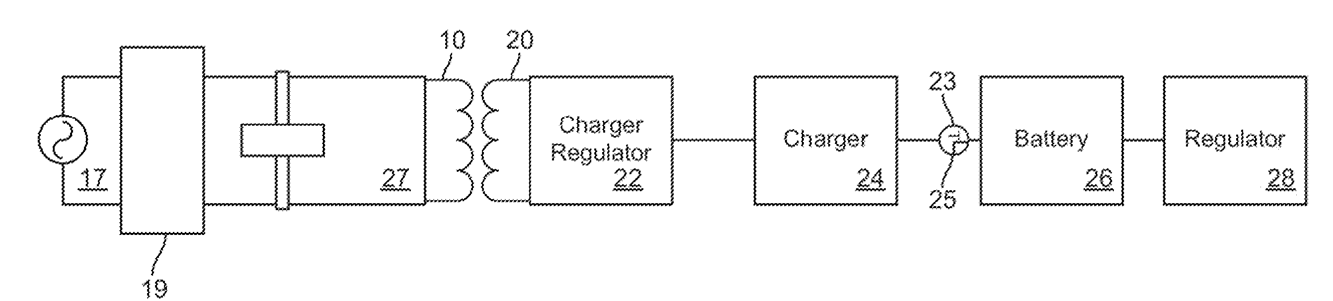
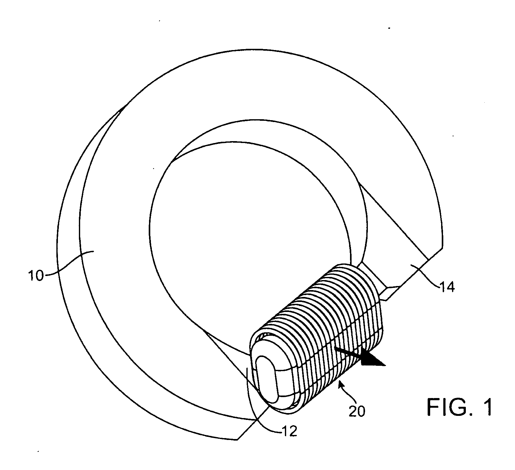
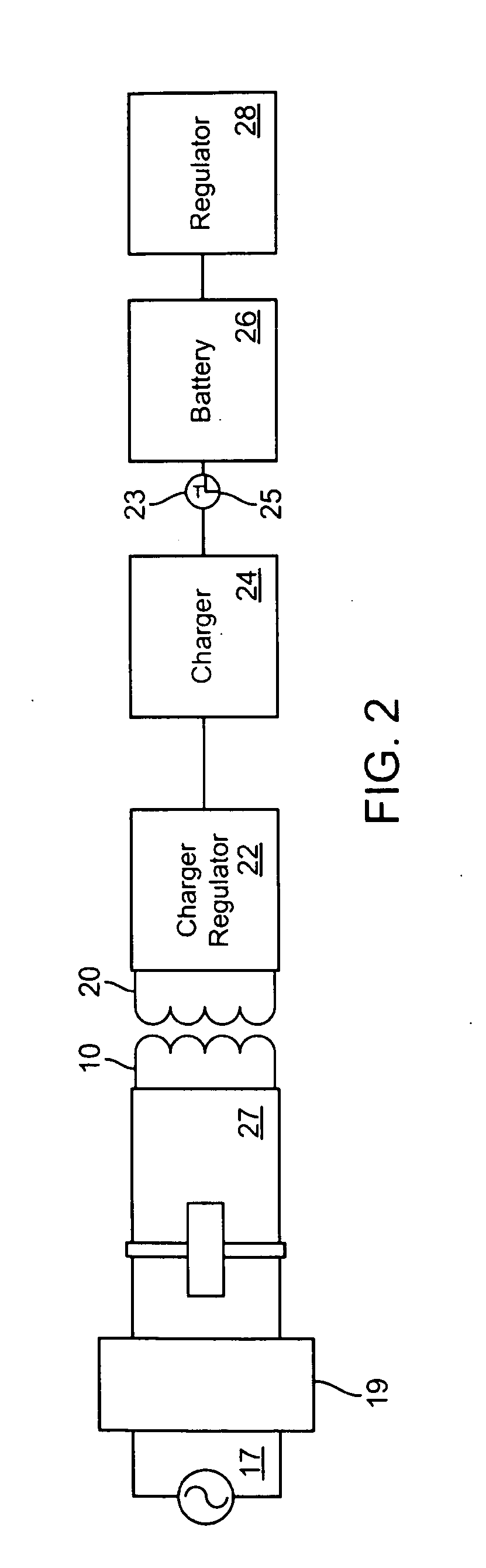
[0025]One embodiment of the present invention is a battery charging system for use with an induction charger to charge a portable appliance such as an intraoral appliance, a head-set, or a behind the ear (BTE) external microphone. As shown in FIG. 1, the battery charging system includes a first coil portion 10 located on a charger base and a second coil portion 20 located on the appliance, such as the BTE device. When the user needs to recharge the battery in the appliance, the user places the second coil portion 20 between two ends 12 and 14 of the first coil portion 10 to complete the magnetic flux loop. The completion of the loop in turn induces current flow on the second coil portion. The current flow is then regulated and used to charge an energy storage device such as a battery or a super-capacitor, among others. Notably, the battery charging system can charge a number of devices. Accordingly, a plurality of such devices can be simultaneously, and efficiently, charged using a ...


PUM


Abstract

Systems and methods are disclosed for charging an intra-oral apparatus includes an intra-oral appliance having an appliance charger coil defining a first portion of an electromagnetic loop; and a charger base having a base charger coil defining a second portion of the electromagnetic loop, wherein the appliance charger coil and the base charger coil in combination transfer energy for inductive charging.

Description

BACKGROUND OF THE INVENTION[0001]Due to the convenience of use and safety through sealed power electronics, induction charging has been used in portable motorized toothbrushes that typically contain a rechargeable battery which is charged by induction. Induction charging systems provide the benefit of recharging the battery of a device without a wired connection. Other portable wireless communication devices, such as two-way RF radios, cellular phones, paging devices, and wireless communicators, commonly utilize a rechargeable battery that, in certain applications, is recharged by contactless induction charging.[0002]U.S. Pat. No. 6,917,182 discloses an inductive charging system with an inductive charger having an inductive charging surface and an alignment feature depicted on a surface of the inductive charger indicating a location of the inductive charging surface. A structural feature may extend substantially perpendicular to the alignment feature and provides a guide for positio...

Claims


Application Information

Patent Timeline
Patent Type & Authority Applications(United States)
IPC IPC(8): H02J7/00
CPCH01F38/14H04R25/55H02J7/025H02J50/10H02J7/0042
Inventor KASSAYAN, REZASPIRIDIGLIOZZI, JOHNABOLFATHI, AMIR
Owner SOUNDMED LLC
Why Eureka
Try Eureka