
System for simplification of reconfigurable beam-forming network processing within a phased array antenna for a telecommunications satellite

a technology of phased array antenna and network processing, which is applied in the direction of individual energised antenna array, particular array feeding system, transmission, etc., can solve the problems of increasing demand, increasing beam-forming complexity and cost, and complex phased arrays, so as to simplify the beam-forming function of phased array and simplify the processing

Active Publication Date: 2010-08-05
ASTRIUM GMBH
View PDF8 Cites 58 Cited by
  • Summary
  • Abstract
  • Description
  • Claims
  • Application Information

AI Technical Summary

Benefits of technology

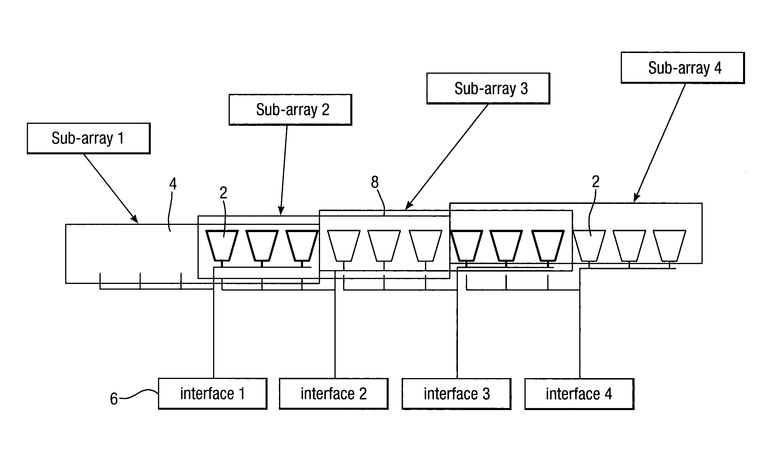
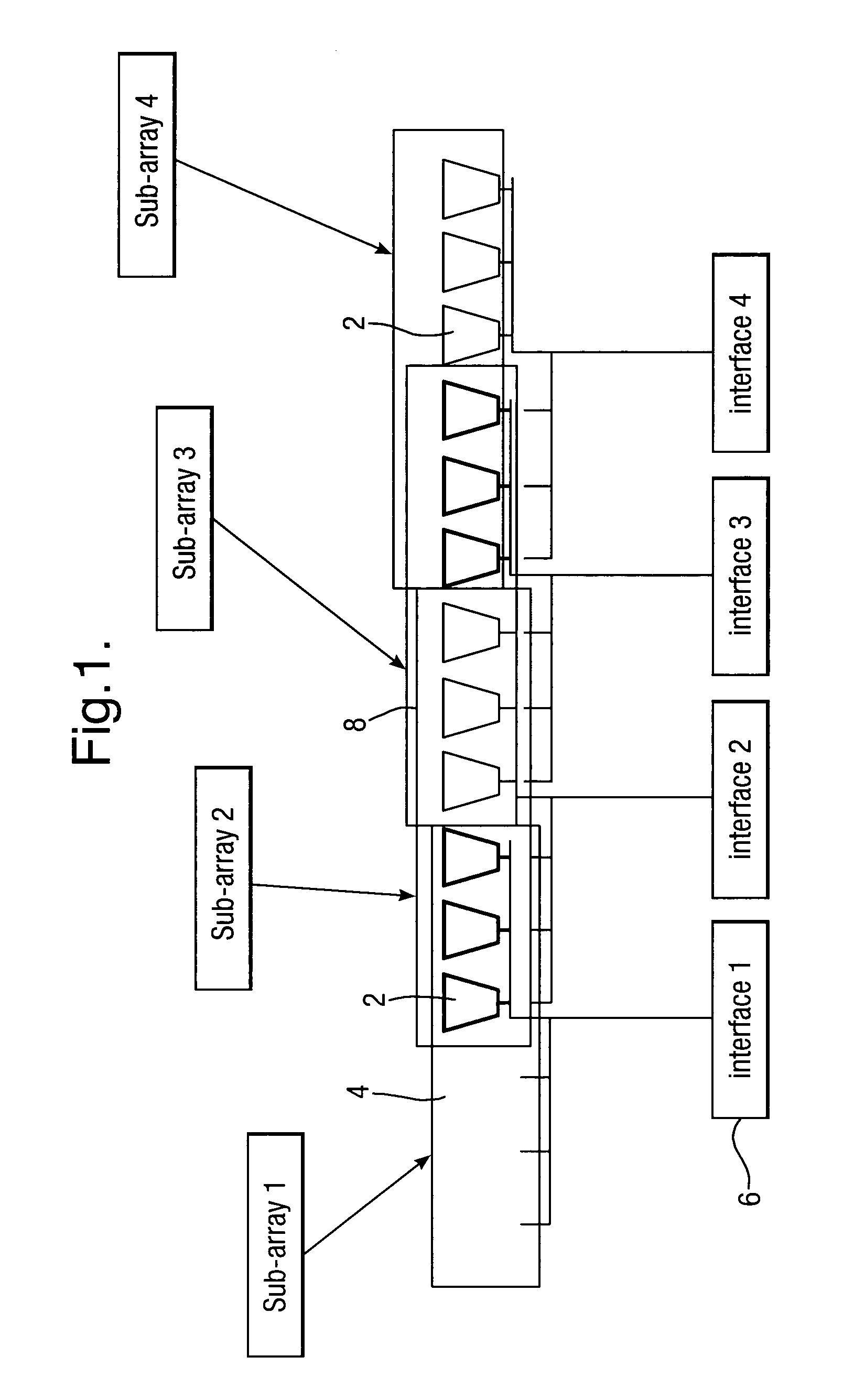
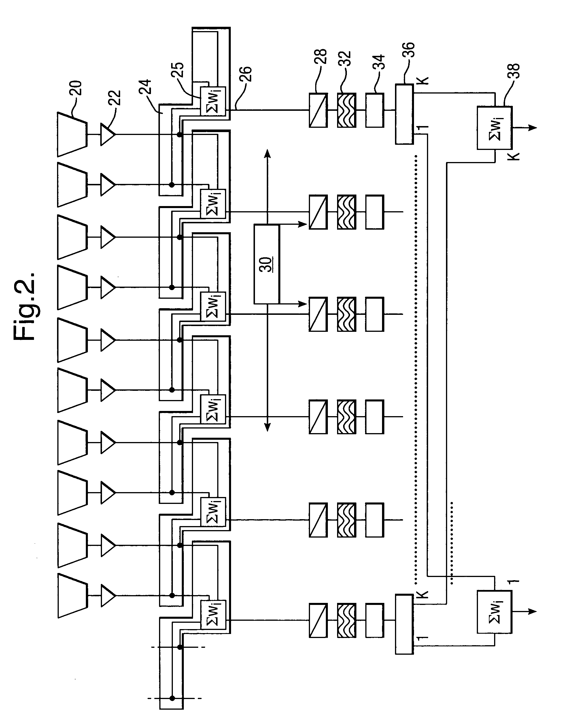
[0032]Thus, the invention provides a scheme by which the beam-forming function within a phased array may be simplified by partitioning it into two stages, in which the sub-array stage (adjacent to the physical array) relates to a fixed, or infrequently changed, set of overlapping sub-arrays and the main stage provides the main pattern reconfiguration, typically in the form of multiple reconfigurable spot beams within a defined coverage region. A key advantage lies in the significant reduction in number of main beam-forming stage control points (at which independent amplitude and phase signals are applied) when compared with a conventional phased array (where amplitude and phase control is applied for each element of the array). In the case that the main beam-forming and associated processing is performed digitally, the reduction in the number of main beam-forming control points simplifies the processing to the extent that the implementation is made feasible within the limits of current digital technology.

Problems solved by technology

An ongoing problem is that, although there are continual improvements in enabling digital processor technologies, there are continually increasing demands in terms of beam-forming and associated processing associated with the need to provide larger numbers of narrower spot beams operating over broader bandwidths.
But it is also well known that phased arrays are complex, massive and expensive.
Compared with alternative antenna types, for instance array-fed reflectors (AFR), they typically require many more radiating elements and thus much greater beam-forming complexity and cost.
Even the next generation of on board digital processors cannot support the complexity needed to provide fully flexible beam-forming for a phased array designed to generate (for instance) beams of diameter 0.5° covering Europe at a frequency of 20 GHz with a bandwidth of 500 MHz, which is a current commercial requirement.

Method used


Image

  • System for simplification of reconfigurable beam-forming network processing within a phased array antenna for a telecommunications satellite
  • System for simplification of reconfigurable beam-forming network processing within a phased array antenna for a telecommunications satellite
  • System for simplification of reconfigurable beam-forming network processing within a phased array antenna for a telecommunications satellite

Examples


example

[0081]Referring to FIG. 8, this shows a desired arrangement for European coverage, of 100 spot beams, Boresight pointed to 17° E, 48.5° N, from geostationary location at 7° E

[0082]For the initial design considerations of the antenna:

[0083]Begin with a DRA aperture of 2.4 m (comparable to the size of an AFR reflector), element spacing 2.12 wavelengths. Element spacing determines how much performance the antenna loses when it is scanned. That is, the drop-off in performance of each individual element between the centre and the edge of the earth results in an irrecoverable performance loss. On the other hand, the smaller the elements, the more of them are required, so, there is a trade off which usually for geostationary satellites results in an element size in the range 2-3 wavelengths.

[0084]Coverage has extent 6.75° E / W, 3.12° N / S

[0085]Element 2.12 wavelength, decimation into overlapping sub-arrays by 3 E / W and 6 N / S on a square element lattice is attempted.

[0086]This results in an a...


PUM


Abstract

A telecommunications satellite having a phased array antenna, wherein the beam-forming function within the phased array is simplified by partitioning it into two stages, in which the sub-array stage relates to a fixed, or infrequently changed, set of overlapping sub-arrays and the main stage provides the main pattern reconfiguration, typically in the form of multiple reconfigurable spot beams within a defined coverage region. The key advantage lies in the significant reduction in number of second stage beam-forming control points (at which independent amplitude and phase is applied) when compared with a conventional phased array (where amplitude and phase control is applied for each element of the array). The sub-array stage beam-forming may be implemented in analogue technology. The main beam-former may be implemented in digital technology, where the key processing functions of A / D or D / A conversion, frequency (de)multiplexing and digital beam-forming all scale with the number of control points.

Description

TECHNICAL FIELD[0001]The present invention relates in general to beam-forming of a phased array antenna for a telecommunications space craft, and in particular relates to the simplification of reconfigurable beam-forming network processing within a phased array antenna for a telecommunications satellite.BACKGROUND ART[0002]A clear trend in satellite communications is towards the use of multiple spot beam coverage in order to provide high gain (to reduce power and operate with small terminals) and to support spatial frequency reuse (to increase throughput within bandwidth constrained systems). It is known accurately to define such narrow spot beams, with a multi-element antenna system, by digital beam-forming techniques involving assigning complex digital weights to the elements for each communication frequency channel for controlling spot beam parameters: see A. M. Bishop et al “The INMARSAT 4 Digital Processor and Next Generation Developments”, 23rd AIAA ICSSC, Rome, Italy, Septemb...

Claims


Application Information

Patent Timeline
IPC IPC(8): H01Q1/28H01Q3/26
CPCH01Q1/288H01Q3/26H01Q25/00H01Q21/061H01Q21/22H01Q21/0006H04B7/18515
Inventor CRAIG, ANTONY DUNCANSTIRLAND, SIMON JOHN
Owner ASTRIUM GMBH
Learn More