Eyeglass lens processing apparatus

a processing apparatus and lens technology, applied in the direction of edge grinding machines, grinding machine components, manufacturing tools, etc., can solve the problems of difficult rapid reduction of torque, large so-called “axial displacement”, and large torque exceeding tolerance, so as to effectively prevent the effect of “axial displacement” and prolonging the processing tim

Active Publication Date: 2010-08-05
NIDEK CO LTD
View PDF13 Cites 19 Cited by
  • Summary
  • Abstract
  • Description
  • Claims
  • Application Information

AI Technical Summary

Benefits of technology

[0007]The present invention is made in view of the above-described problems, and it is therefore an object of the invention to provide an eyeglass lens processing apparatus capable of effectively preventing the “axial displacement” from occurring without lengthening the processing time.

Problems solved by technology

In the processing control that is similar to that of lenses not having any water-repellent substance coated thereon, since the surface of the water-repellent lens is slippery, the attaching position of the cup slips when a rough-grinding wheel is deeply cut in the lens, and the axial angle (that is, the rotation angle of the lens) of the lens comes off with respect to the rotation angle of the lens chuck shaft, wherein there is a problem that a so-called “axial displacement” greatly occurs.
According to the technique of JP-A-2004-255561, the load torque rapidly exceeds the tolerance of the load torque applied to the lens when the cutting depth increases, and it would be difficult to quickly decrease the torque.
Further, if it is controlled that the torque is decreased by rapidly moving the lens away from the grinding wheel, there may be cases where the lens chuck shaft oscillates in the up and down directions.
If the cutting depth is constant, there may be cases where the load torque applied onto the lens chuck shaft exceeds the tolerance at a thick portion of the lens.

Method used


Image

  • Eyeglass lens processing apparatus
  • Eyeglass lens processing apparatus
  • Eyeglass lens processing apparatus

Examples


Embodiment Construction

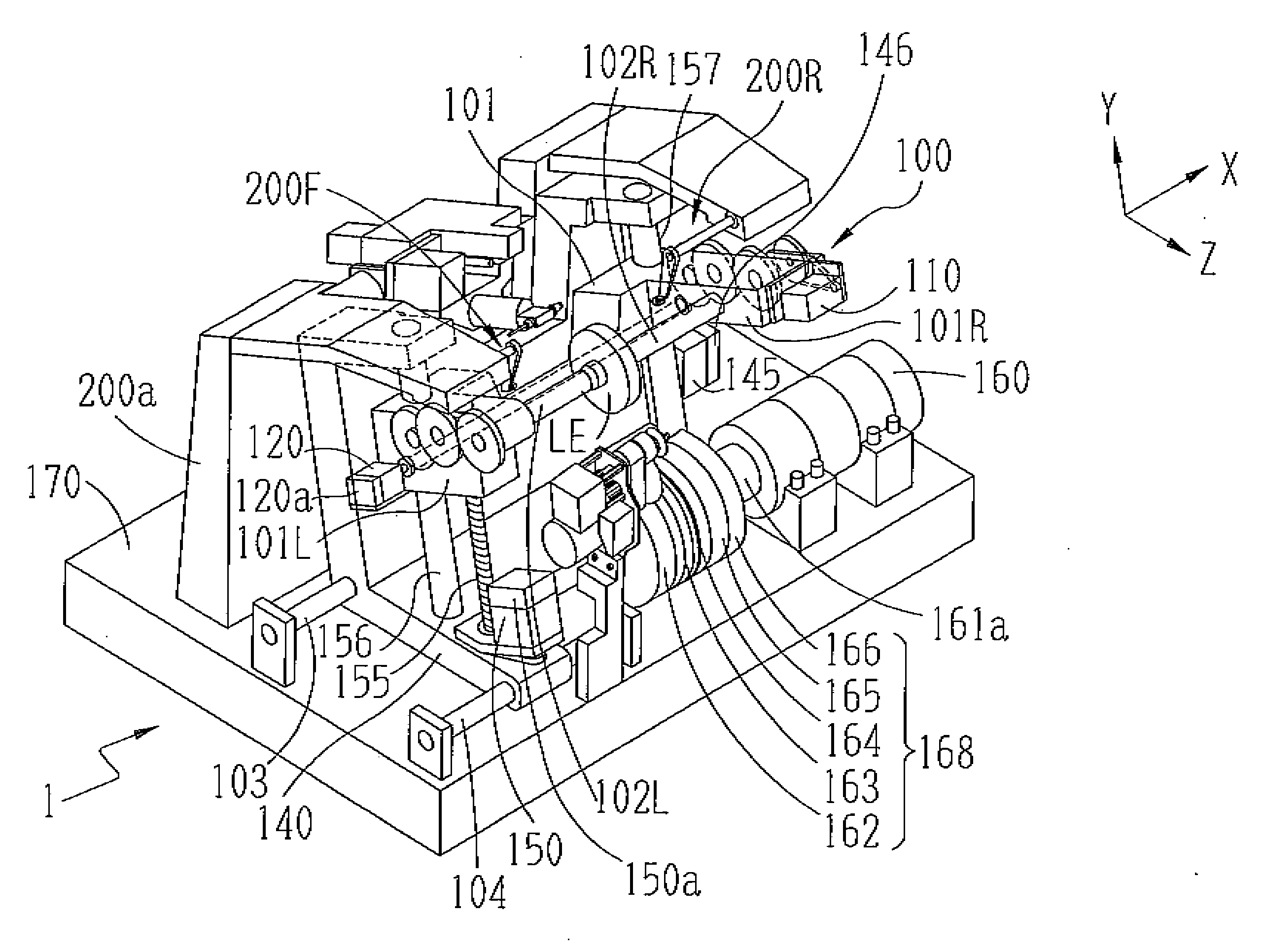
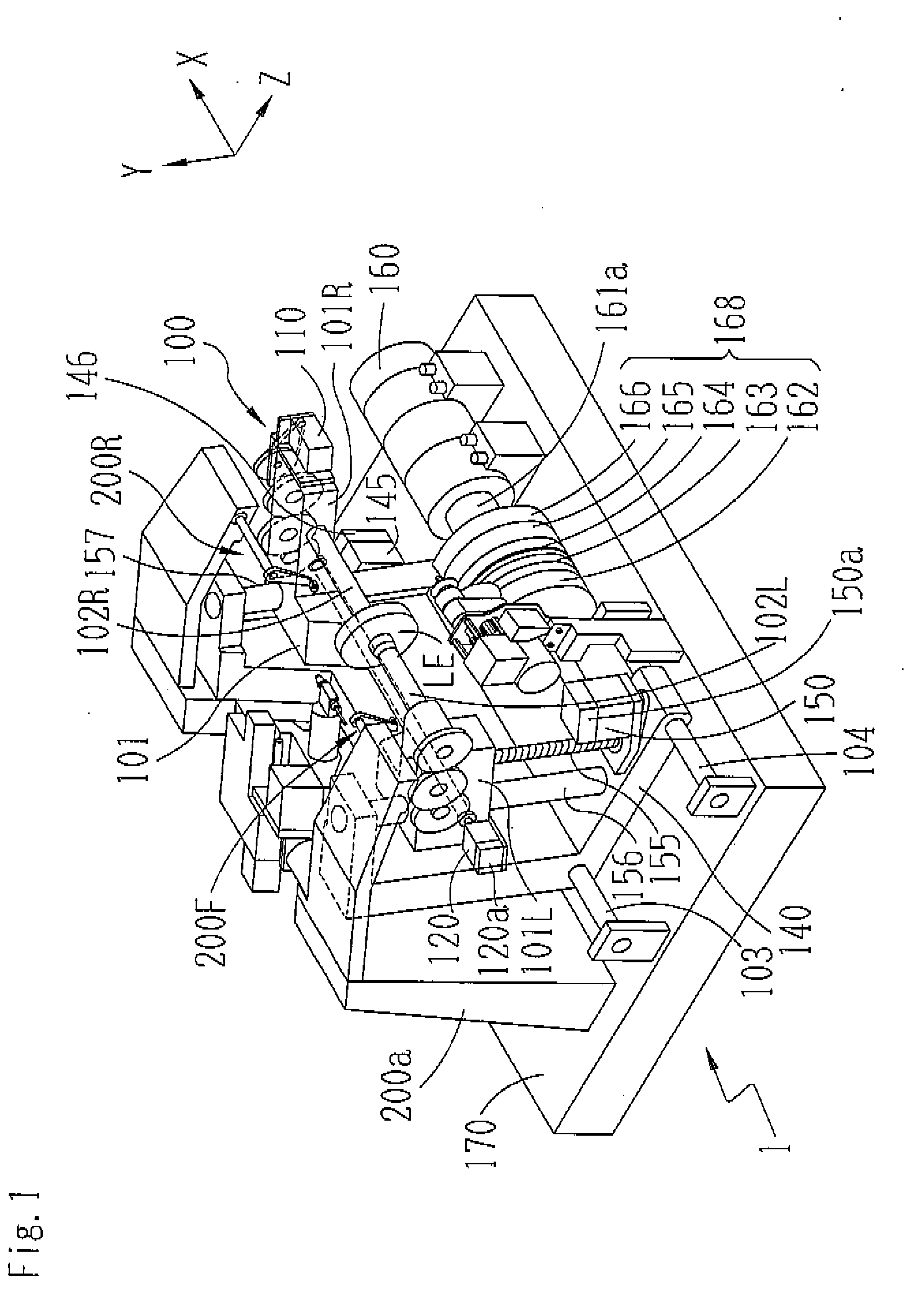
[0040]Hereinafter, a description is given of an exemplary embodiment of the present invention. FIG. 1 is a schematic configuration view of a processing portion of an eyeglass lens processing apparatus according to the invention.

[0041]A carriage portion 100 is mounted on a base 170 of a processing apparatus main body 1. A periphery of a lens LE to be processed, which is placed between a pair of lens chuck shafts 102L and 102R supported by the carriage 101 holds is pressed against a grinding wheel group 168 of a processing tool coaxially attached to the shaft 161a to be processed. The grinding wheel group 168 includes a rough-grinding wheel 162 for glass, a finish-grinding wheel 163 including a bevel inclination to bevel a high-curve lens for high curve beveling, a finish-grinding wheel 164 having a V groove (bevel) VG and a flat-processed surface to bevel a low-curve lens, a flat mirror-finish grinding wheel 165, and a rough-grinding wheel 166 for plastic. The grinding wheel shaft 16...


PUM

PropertyMeasurementUnit
radius vector lengthaaaaaaaaaa
distanceaaaaaaaaaa
outer diameteraaaaaaaaaa

Abstract

An eyeglass lens processing apparatus includes: a lens rotation unit rotating a lens; a processing tool rotation unit processing the lens; an axis-to-axis distance changing unit for changing an axis-to-axis distance between the chuck shaft and the processing tool rotation shaft; a lens surface configuration acquiring unit which acquires a front surface curve configuration and a rear surface curve configuration of the lens; a lens outer diameter acquiring unit which acquires an outer diameter of a lens; a calculation unit which calculates a thickness of the lens and calculates a cutting depth of the lens, so that torque applied onto the chuck shaft in rough processing becomes substantially constant, based on the calculated lens thickness and a processing distance from the rotation center of the lens; and a control unit which controls the axis-to-axis distance changing unit in accordance with the calculated cutting depth and for rough processing the lens.

Description

BACKGROUND[0001]The present invention relates to an eyeglass lens processing apparatus for processing the periphery of an eyeglass lens.[0002]In an eyeglass lens processing apparatus, an eyeglass lens is held by a pair of lens chuck shafts, the lens is rotated by rotation of the lens chuck shafts, and the periphery of the lens is roughly processed by being pressed to a rough-grinding wheel. When the eyeglass lens is held by the lens chuck shafts, a cup being the fixing jig is fixed on the surface of the lens, and the lens is mounted on a cup holder of one chuck shaft via the cup, and the lens is chucked by a lens holding member of the other lens chuck shaft.[0003]In recent years, a water-repellent lens having a water-repellent substance coated on the lens surface, to which water and oily substances are hardly adhered, has been frequently used. In the processing control that is similar to that of lenses not having any water-repellent substance coated thereon, since the surface of the...

Claims


Application Information

Patent Timeline
Patent Type & Authority Applications(United States)
IPC IPC(8): B24B51/00
CPCB24B9/148
Inventor TAKEICHI, KYOJI
Owner NIDEK CO LTD
Why Eureka
Try Eureka