Hybrid vehicle driving system, hybrid vehicle, and driving method

a hybrid vehicle and driving system technology, applied in the direction of process and machine control, instruments, etc., can solve the problems of limited fuel types, high noise, and inability to overcome the internal combustion engine, and achieve the effect of low high reaction rate of output adjustment, and short tim

Inactive Publication Date: 2010-08-05
XINCTEC TECH LLC
View PDF64 Cites 8 Cited by
  • Summary
  • Abstract
  • Description
  • Claims
  • Application Information

AI Technical Summary

Benefits of technology

[0026]The external combustion engine is low in reaction rate of output adjustment, and it takes a long time to output a required output value. Meanwhile, the electric motor is high in reaction rate of output adjustment, and can output a required output value in a short time.
[0035]When both the power output by the external combustion engine and the power output by the electric motor are selected as the power to be transmitted to the wheel, and the output value output by the external combustion engine is extremely smaller than the output value to be output by the external combustion engine, the power selection device increases the output value output by the electric motor. In this case, the wheel is driven mainly by the power output by the electric motor. Meanwhile, the power selection device reduces the output value output by the electric motor when the output value output by the external combustion engine is close to the output value to be output by the external combustion engine. In this case, the wheel is driven mainly by the power output by the external combustion engine.

Problems solved by technology

However, the conventional hybrid vehicle has a problem that disadvantages of the internal combustion engine cannot be overcome such as high noise due to combustion and explosion of fuel, limitation on types of fuel, or difficulty in reducing exhaust gas containing pollutants.
However, the external combustion engine has a disadvantage that a reaction rate of output adjustment is lower than that of the internal combustion engine.
However, in the electric vehicle described in Japanese Patent Application Laid-Open No. 2003-239804, the power output by the external combustion engine is never transmitted to the wheels.
Thus, there is a problem of loss arising for the power output by the external combustion engine to be once converted into electric power.
The external combustion engine is low in reaction rate of output adjustment, and it takes a long time to output a required output value.

Method used


Image

  • Hybrid vehicle driving system, hybrid vehicle, and driving method
  • Hybrid vehicle driving system, hybrid vehicle, and driving method
  • Hybrid vehicle driving system, hybrid vehicle, and driving method

Examples


Embodiment Construction

[0067]The present disclosure will be described in detail based on the drawings showing an embodiment thereof.

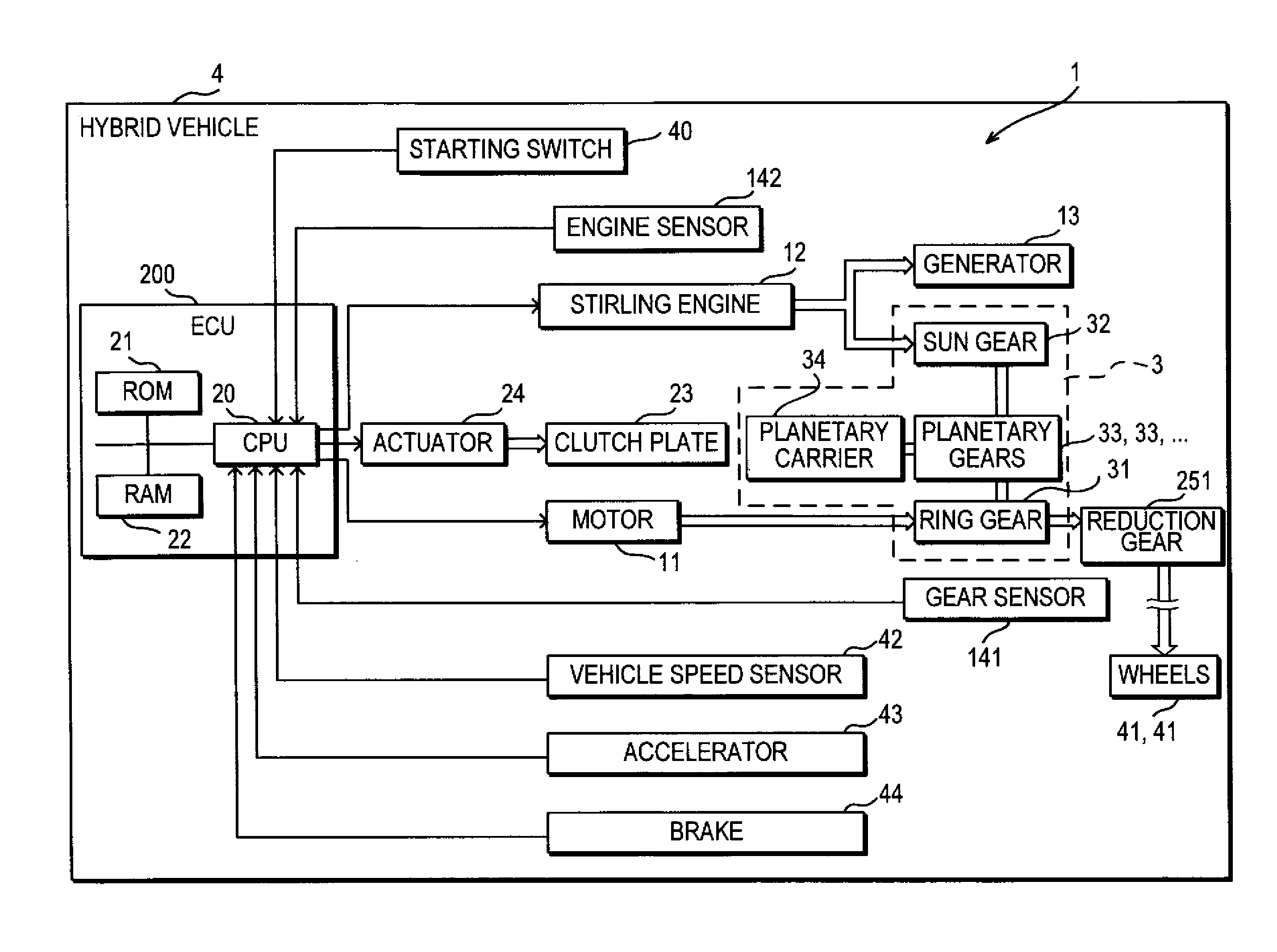
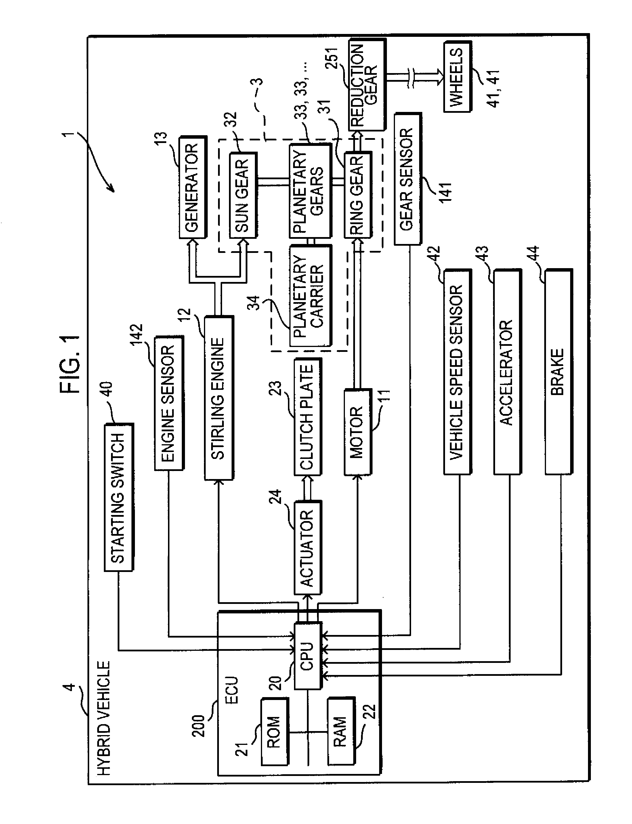
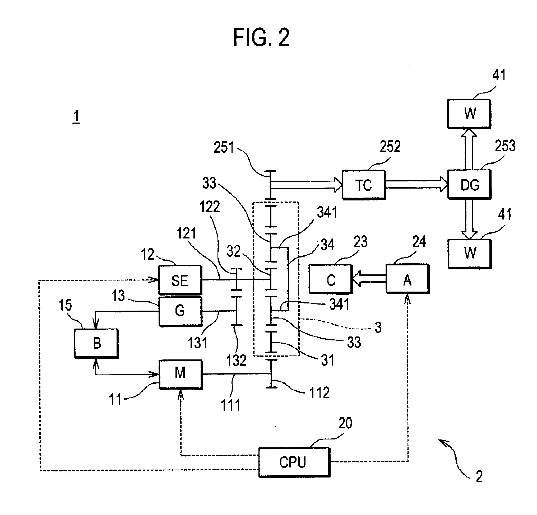
[0068]FIG. 1 is a block diagram showing an essential part configuration of a hybrid vehicle 4 according to an embodiment of the present disclosure, and FIG. 2 is a schematic illustrative view showing an essential part configuration of a hybrid vehicle driving system 1 according to the embodiment of the present disclosure.

[0069]The hybrid vehicle 4 according to this embodiment is a front-wheel-drive four-wheel vehicle, but not limited to this. For example, the hybrid vehicle 4 may be various vehicles with two to four wheels, an agricultural vehicle, a railway vehicle, a play vehicle such as a go-cart, or the like.

[0070]The hybrid vehicle 4 includes at least a hybrid vehicle driving system 1 having an CPU (Central Processing Unit) 20, a starting switch 40, wheels 41 and 41, a vehicle speed sensor 42, an accelerator 43, and a brake 44. A driving method according to the embodimen...


PUM


Abstract

When a driver turns on an accelerator, a CPU permits revolution of planetary gears, and a motor rotates a ring gear to drive wheels. Then, when the driver turns off the accelerator, the CPU calculates a target RPM to be output by a Stirling engine according to a depression amount and a depression time of the accelerator. When the RPM output by the Stirling engine reaches close to the target RPM, the revolution of the planetary gears is inhibited, the operation of the motor is stopped, and the Stirling engine rotates the ring gear via a sun gear and the planetary gears to drive the wheels.

Description

CROSS-REFERENCE TO RELATED APPLICATIONS[0001]This Nonprovisional application claims priority under 35 U.S.C. §119(a) on Patent Application No. 2009-20767 filed in Japan on Jan. 30, 2009, the entire contents of which are hereby incorporated by reference.BACKGROUND[0002]1. Technical Field[0003]The present disclosure relates to a hybrid vehicle driving system that transmits power output by two types of power sources having different characteristics to wheels, a hybrid vehicle, and a driving method.[0004]2. Description of Related Art[0005]In recent years, a hybrid vehicle including two types of power sources having different characteristics has been put to practical use. The hybrid vehicle is configured so as to run with power output by the two types of power sources optimally combined depending on circumstances to make the most of advantages of the power sources and compensate for disadvantages thereof.[0006]The conventional hybrid vehicle includes an internal combustion engine and an ...

Claims


Application Information

Patent Timeline
Patent Type & Authority Applications(United States)
IPC IPC(8): G06F19/00B60K6/24B60K6/365B60K6/445B60L50/16B60W10/06B60W10/08B60W20/00F16H3/54
CPCB60K6/445B60L2200/26B60L2240/443B60L2240/486B60W10/06B60W10/08B60W20/00B60W2510/0638B60W2510/0657B60W2540/10B60W2710/0644B60W2710/1061Y02T10/6239Y02T10/6286Y02T10/6295B60L2240/441Y02T10/62B60W2710/086B60W2510/0666B60W10/10B60W20/30B60W2720/28
Inventor ISHII, NORIAKI
Owner XINCTEC TECH LLC
Why Eureka
Try Eureka