
Modular solar photovoltaic canopy system for development of rail vehicle traction power

a solar photovoltaic and solar panel technology, applied in the field of land motor vehicles, can solve the problems of insufficient speed and service life of carbon free renewable energy generating plants such as wind, solar, nuclear or other, and achieve the effect of increasing the control level of their carbon footprint and cost of traction power

Inactive Publication Date: 2010-08-12
DEARBORN DAVID DAYTON
View PDF6 Cites 11 Cited by
  • Summary
  • Abstract
  • Description
  • Claims
  • Application Information

AI Technical Summary

Benefits of technology

[0009]A system of solar PV canopy modules positioned over rail tracks can provide a method by which rail system operators can become Carbon Neutral, or make some portions of those systems Carbon Neutral; and in the process, offer rail operators an increased level of control over their carbon footprint and cost of traction power.
[0011]Example of one benefit: Energy production from an urban or regional solar PV canopy over rail right of way during periods of peak demand coincides with the canopy's periods of peak power output. During periods of peak demand, a carbon neutral modular solar PV canopy system over railroad tracks or right of way can produce 40% to 50% more electrical power than required for traction power of said rail vehicles. This surplus energy going into the local grid will reduce the need for carbon based peak generating plants and the probability of reduced electrical supply service levels.
[0014]b) assist the local power grid supplier in reducing its carbon footprint,

Problems solved by technology

Periods of hot weather or peak electrical demand strain electrical producing capacities or cause reductions in service.
U.S. Department of Energy projections state that carbon free renewable energy generating plants such as wind, solar, nuclear or other will not come on line fast enough to meet this growing demand.

Method used


Image

  • Modular solar photovoltaic canopy system for development of rail vehicle traction power
  • Modular solar photovoltaic canopy system for development of rail vehicle traction power
  • Modular solar photovoltaic canopy system for development of rail vehicle traction power

Examples


Embodiment Construction

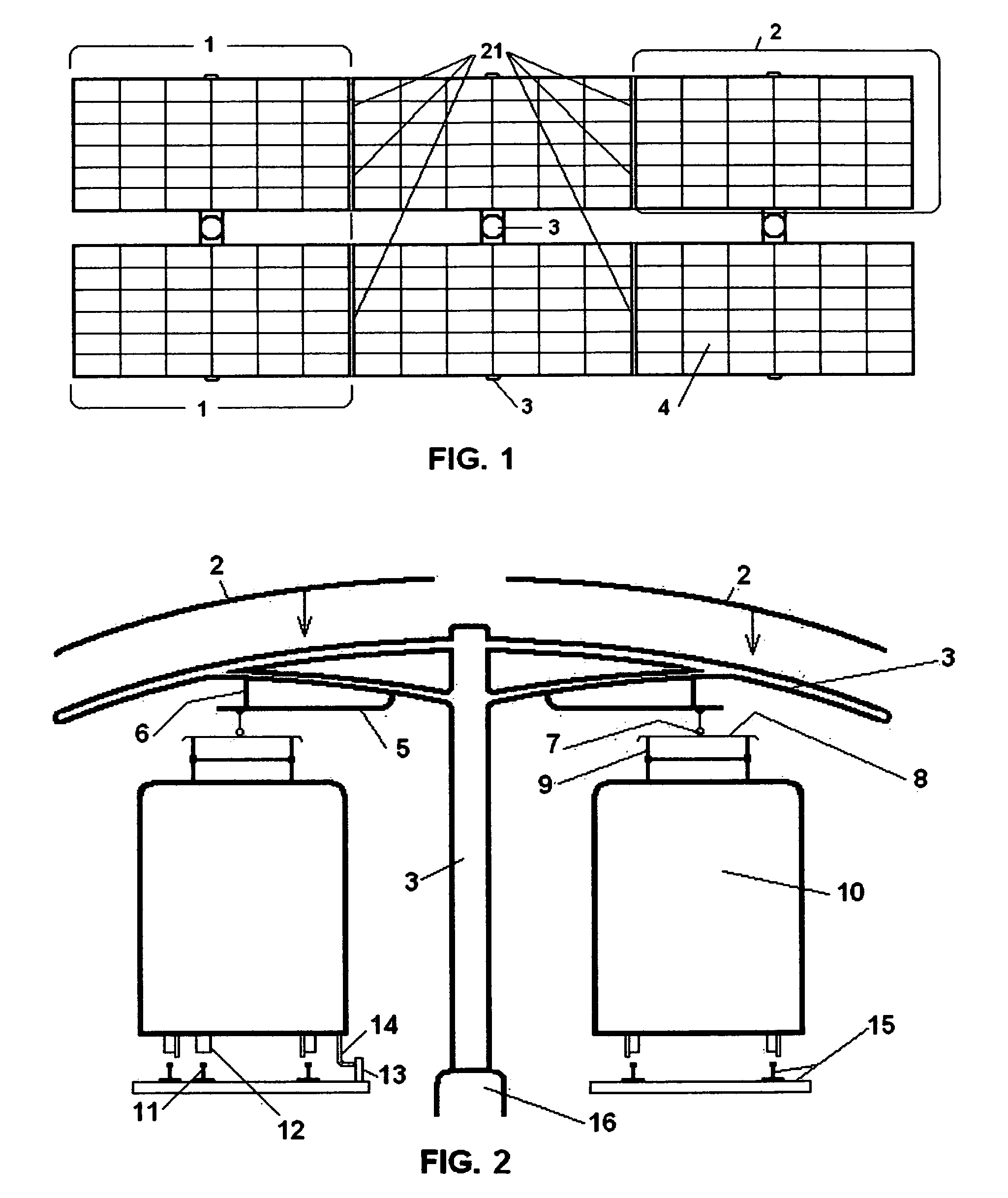
[0025]Although the following descriptions FIG. 1 through 4 contain some specific details for the purpose of illustration, anyone of ordinary skill in the art and the field of solar PV canopy and structural design, and the field of power electrical engineering will appreciate that variations and alterations to the following presentations herein are within the scope of this invention.

[0026]Accordingly, the embodiments of the invention described below are set forth without any loss of generality to, and without imposing limitations upon, the claimed invention.

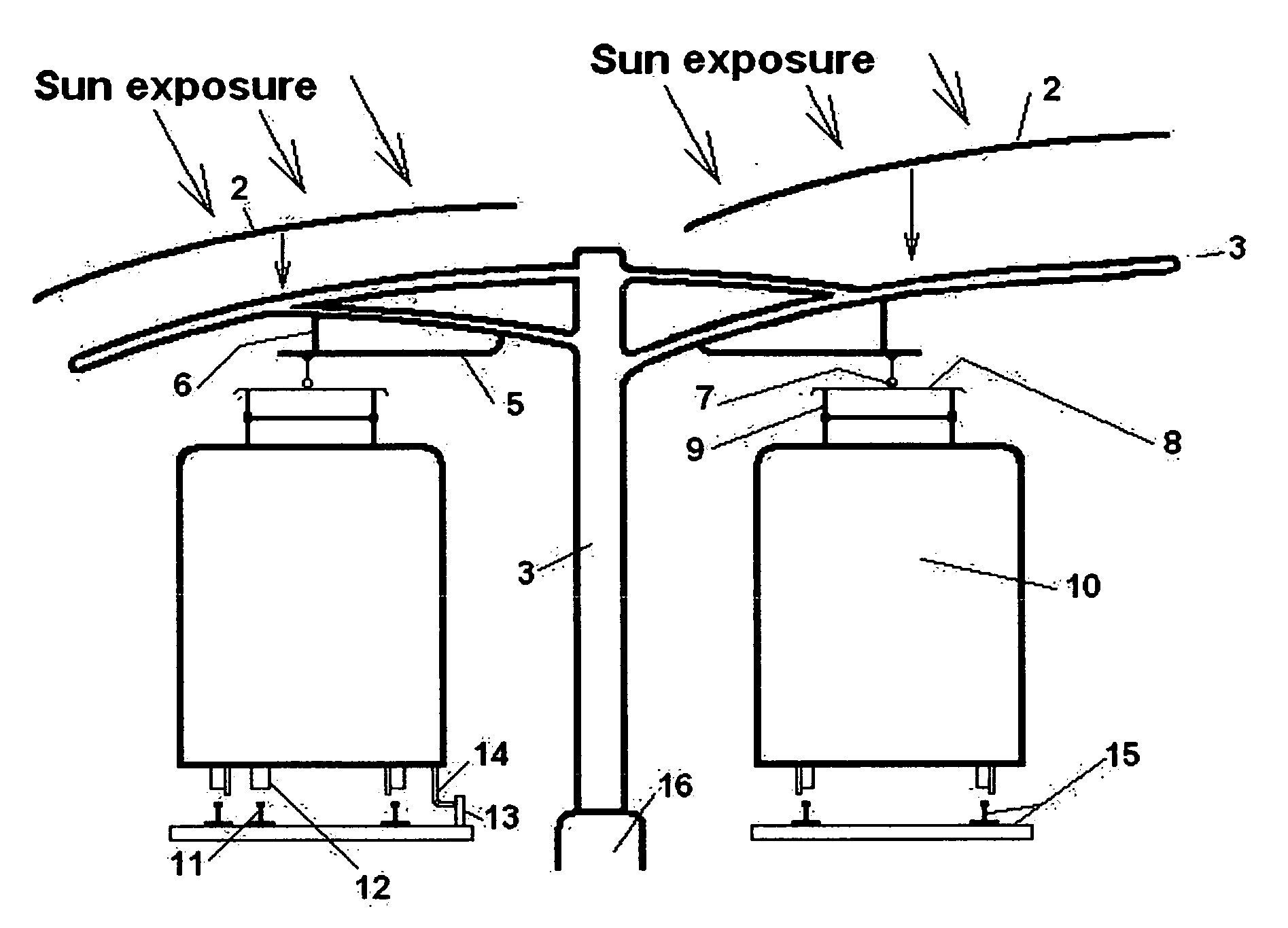
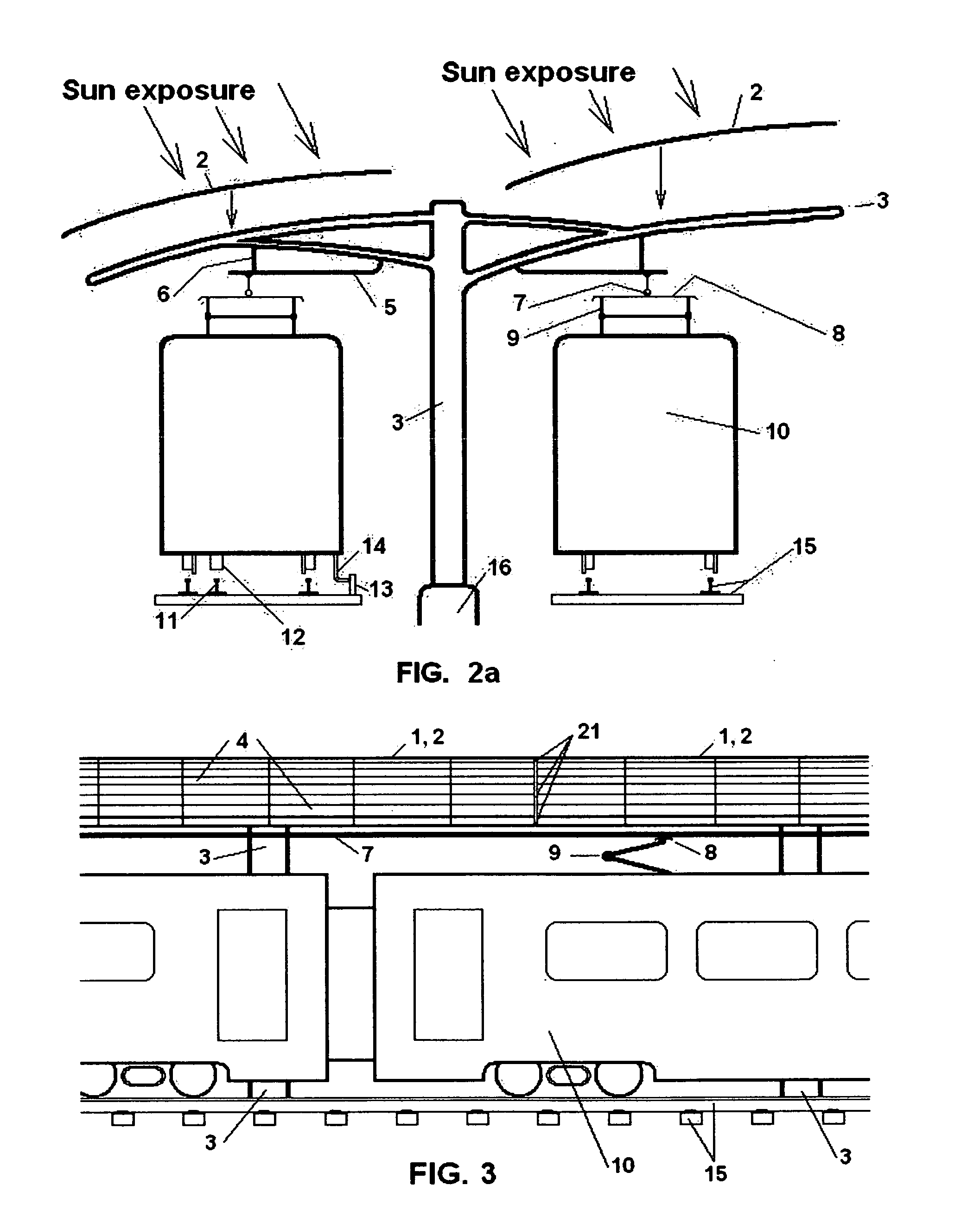
[0027]Embodiments of the present invention relate to the integration of solar photovoltaic technology and products derived there from with the available use of air rights (space above) a rail operator's tracks and owned right-of-way, and doing so concurrently with full operation of said right-of-way for the purpose of producing carbon free electrical power.

[0028]Solar PV canopy designs are not new. Solar PV canopy designs for inst...


PUM


Abstract

This invention provides a method by which rail systems can use air space above tracks and right of way for generating traction power for electric powered rail vehicles. Through the design and installation of rail-specific solar photovoltaic canopy modules, replicated and joined together in assemblies of various lengths, transit districts, rail agencies and operators can develop energy for rail vehicle traction power. Integrating solar PV technology and the supply and distribution of traction power can provide a rail system increased levels of energy independence, lower fixed energy cost over 25 to 30 years and the possibility of providing Carbon Neutral rail service.

Description

[0001]This application claims priority from U.S. provisional patent application No. 61 / 192,871 filed Sep. 23, 2008.TECHNICAL FIELD[0002]The present invention relates to the field of land motor vehicles where said motor(s) is supplied with power from an external source, and that source of power is derived from the sun, a freely occurring natural force.BACKGROUND[0003]The present invention provides a means by which rail (railroad) transportation operators can generate megawatts of carbon free electrical power from the space over rail tracks and right-of-way without buying or leasing significant amounts of sun accessible space or power transmission right of way.[0004]Public rail transportation is becoming increasingly important in the effort to lower carbon emissions from automobile usage. Public rail transportation is migrating from diesel electric locomotive to electric module unit (EMU) vehicles as they operate more efficiently, create less noise and are less dependant on carbon bas...

Claims


Application Information

Patent Timeline
IPC IPC(8): H01L31/042
CPCB60L5/18B60L8/003B60L2230/22B60M3/00H02J3/38Y02E10/50Y02T10/7094Y02T90/12Y04S10/126Y02E60/721H02S20/00B60L2200/26Y02T10/7083B60L53/51H02S20/10Y02T10/70Y02T10/7072Y02E60/00
Inventor DEARBORN, DAVID DAYTON
Owner DEARBORN DAVID DAYTON
Learn More