Liquid cooled compliant heat sink and related method

a heat sink and liquid cooling technology, applied in the field of heat sinks for cooling ic chips and packages, can solve the problems of significant reduction in thermal performance, the ability to remove heat from the chip, and the ic chip being exposed to high temperatures

Inactive Publication Date: 2010-08-12
IBM CORP
View PDF18 Cites 20 Cited by
  • Summary
  • Abstract
  • Description
  • Claims
  • Application Information

AI Technical Summary

Benefits of technology

[0012]A structure and method for providing improved cooling of a substrate, which may be an integrated circuit (IC) chip during test and burn-in, an IC chip or package in a computer, or another substrate, are disclosed.

Problems solved by technology

The high power testing exposes the IC chip to high temperatures.
In addition, higher burn-in powers result in higher heat gradients across the IC chip.
LTIs function to minimize the occurrence of any air gaps between the two surfaces, which would result in a significant reduction in thermal performance and the ability to remove heat from the chip.
However, PAO oils can degrade at the high temperatures and long times necessary for burn-in testing.
Despite excellent thermal performance, they have not proven suitable for use at high temperatures, and can cause corrosion of sensitive devices.
The use of LTIs as a cooling solution further poses a risk of corrosion of the controlled collapse chip connection (C4) as a result of LTI entering the C4 cage.
The use of this cooling solution requires that the testing capabilities be reduced in order to avoid overheating the chip, thus making it inappropriate for future generations of IC chips with smaller features.
The larger the gap between the heat sink and the IC chip, the less efficient the cooling means will be.

Method used


Image

  • Liquid cooled compliant heat sink and related method
  • Liquid cooled compliant heat sink and related method
  • Liquid cooled compliant heat sink and related method

Examples


Embodiment Construction

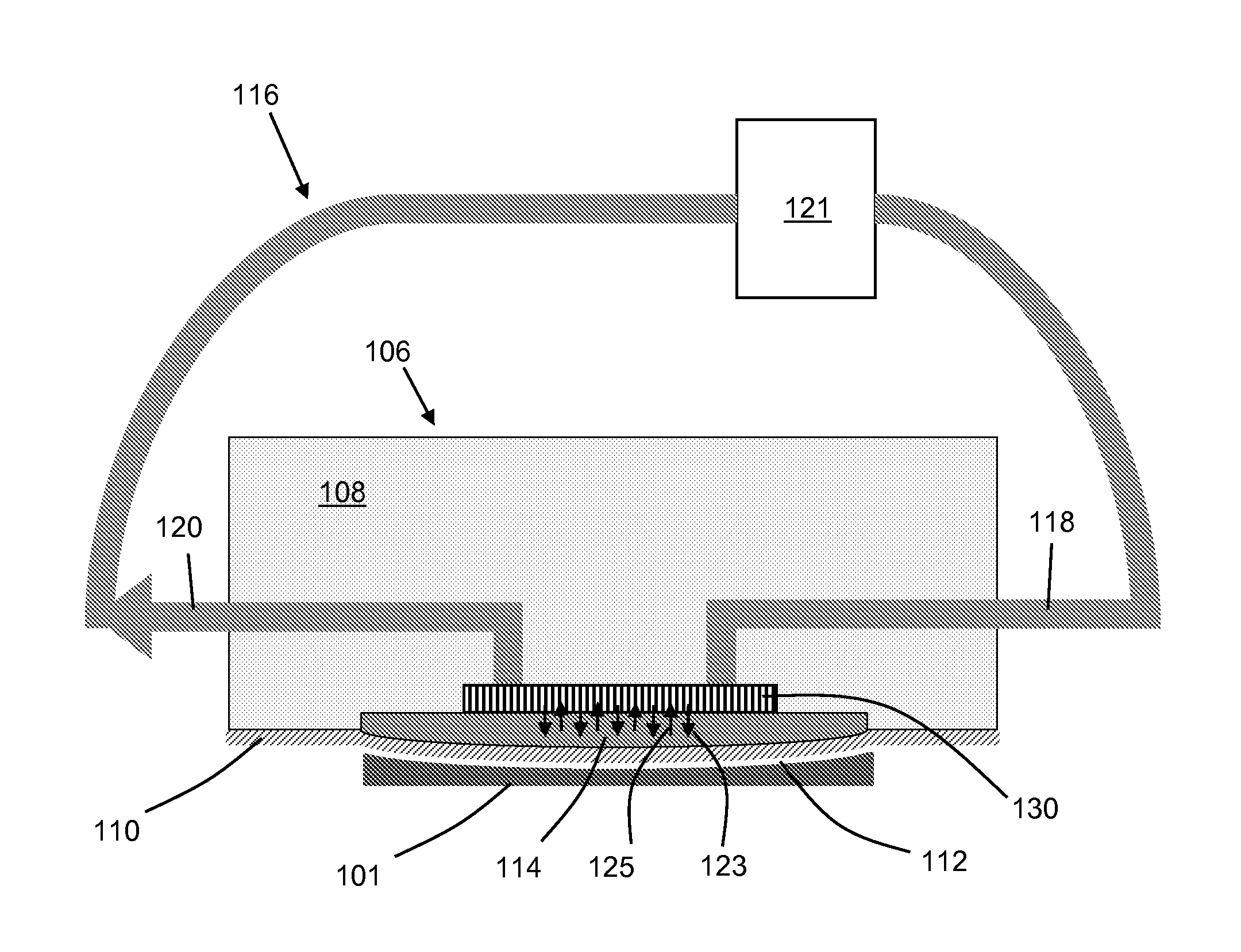
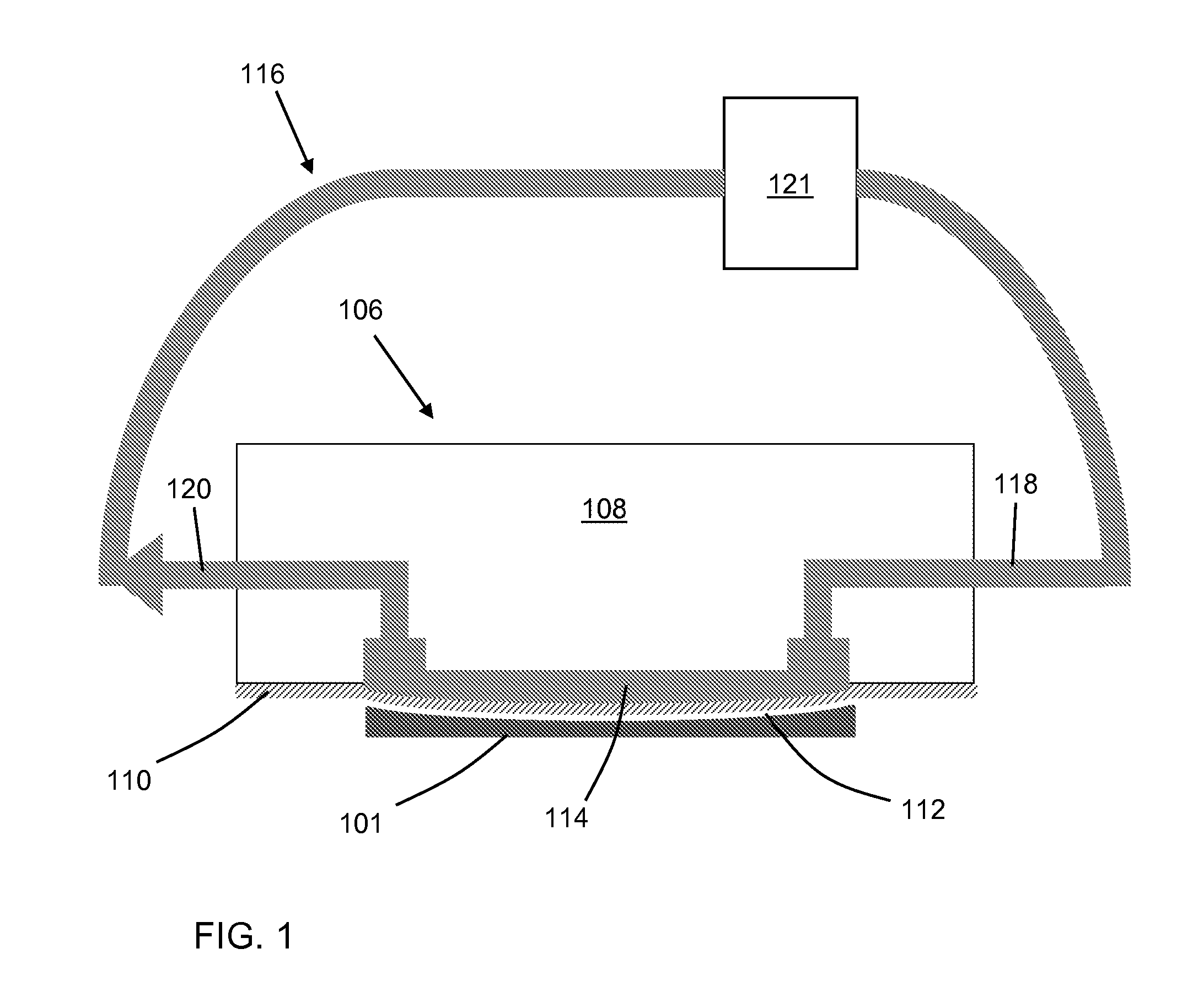
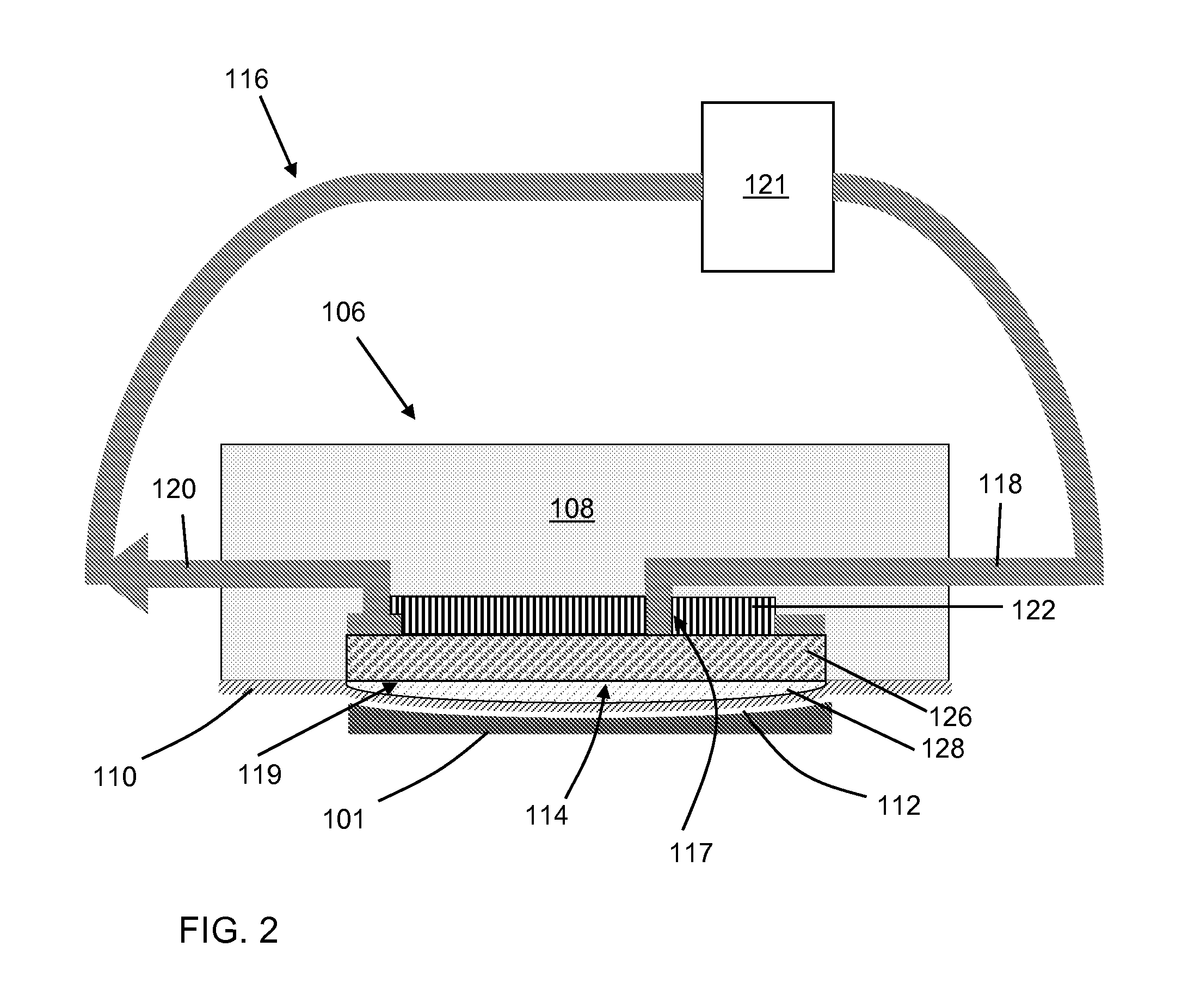
[0021]Referring to the drawings, embodiments of the structure and method according to the disclosure are shown in FIGS. 1-3.

[0022]Turning to FIG. 1, a detailed view of an embodiment of heat sink 106 according to embodiments of the invention is shown. Heat sink 106 includes a manifold block 108, which may be copper. In various other embodiments, manifold block 108 may be aluminum, stainless steel, plastic, ceramic and / or may be plated with various materials, including but not limited to nickel, gold, and silver. A compliant foil 110 is affixed to manifold block 108, forming an interface 112 between heat sink 106 and a surface of IC chip 101. Compliant foil 110 is thin, and made of a thermally conductive material. Foil 110 may be made of beryllium copper (BeCu) and may measure approximately 75 μm in thickness, however, in various alternative embodiments, foil 110 may be made of other conductive materials including but not limited to copper, indium, gold, silver, and stainless steel, a...


PUM


Abstract

A heat sink and method for using the same for use in cooling an integrated circuit (IC) chip is provided herein. The heat sink includes a manifold block, a liquid-filled cooling system, and a compliant foil affixed to the manifold block and backed by a liquid in the closed loop cooling system. The pressure provided by the liquid behind the foil causes the foil to bow, and to conform to non-planarities in the surface of the IC chip, thus reducing air gaps and increasing thermal coupling between the IC chip and the heat sink.

Description

[0001]This non-provisional application claims the benefit of the provisional application filed with the U.S. Patent and Trademark Office as Ser. No. 61 / 150,914 entitled “Liquid Cooled Compliant Heat Sink And Related Method”, filed Feb. 9, 2009.BACKGROUND[0002]1. Technical Field[0003]The disclosure relates generally to integrated circuit (IC) chip packaging, testing, and use in computer hardware. More particularly, it relates to a heat sink for cooling IC chips and packages, including a compliant foil surface backed by a liquid-filled cooling system; and a related method.[0004]2. Background Art[0005]During integrated circuit (IC) chip fabrication and packaging, IC chips are tested and burned in at high power to determine whether they perform as required. The high power testing exposes the IC chip to high temperatures. As IC chip feature sizes have continually decreased, more power is required for driving a unit area of silicon (Si) devices, resulting in increased heat generation. In ...

Claims


Application Information

Patent Timeline
Patent Type & Authority Applications(United States)
IPC IPC(8): H01L23/473F28D15/00F28D11/06H01L23/433
CPCF28D15/00F28F13/00H01L23/3733H01L23/473H01L23/4735H01L2924/0002F28F2013/006H01L2924/00
Inventor BEZAMA, RASCHID J.LONG, DAVID C.NATARAJAN, GOVINDARAJANWEISS, THOMAS
Owner IBM CORP
Why Eureka
Try Eureka