
Distillation apparatus

a technology of distillation apparatus and water tank, which is applied in the direction of lighting and heating apparatus, indirect heat exchangers, water/sludge/sewage treatment, etc., can solve the problems of ineffective and impractical plant operation, inability to efficiently and inability to effectively treat heavily contaminated liquids such as sea water. , the effect of odour and/or unpleasant aftertaste of the treated water

Inactive Publication Date: 2010-08-12
EQUUS ENVIRONMENTAL
View PDF16 Cites 34 Cited by
  • Summary
  • Abstract
  • Description
  • Claims
  • Application Information

AI Technical Summary

Problems solved by technology

These high operating costs can make such plants prohibitively expensive and impractical, particularly for applications in developing countries and in locations without a reliable energy supply.
In addition, known methods of liquid treatment such as reverse osmosis, utilising activated carbon filtration and optionally ultra-violet or ozone exposure, typically do not have the capacity for efficient treatment of heavily contaminated liquids such as sea water or brackish water and usually require pre-treatment such as pre-filtration and / or chemical treatment.
Such known treatment methods produce waters which have total dissolved solid (TDS) concentrations of 500 to 1000 ppm which can result in treated water with odour and / or unpleasant aftertaste and is too saline to use for agricultural irrigation.
Additionally, filtration can lead to operational problems such as filter clogging and the need for sterilisation of the filtration apparatus on a regular basis to prevent build-up of mould, algae and bacteria contaminants.
A further disadvantage with known liquid treatment systems is the lack of portability to a site and scalability on site in situations where increased capacity is required quickly such as in emergency relief situations.

Method used


Image

  • Distillation apparatus
  • Distillation apparatus
  • Distillation apparatus

Examples


Embodiment Construction

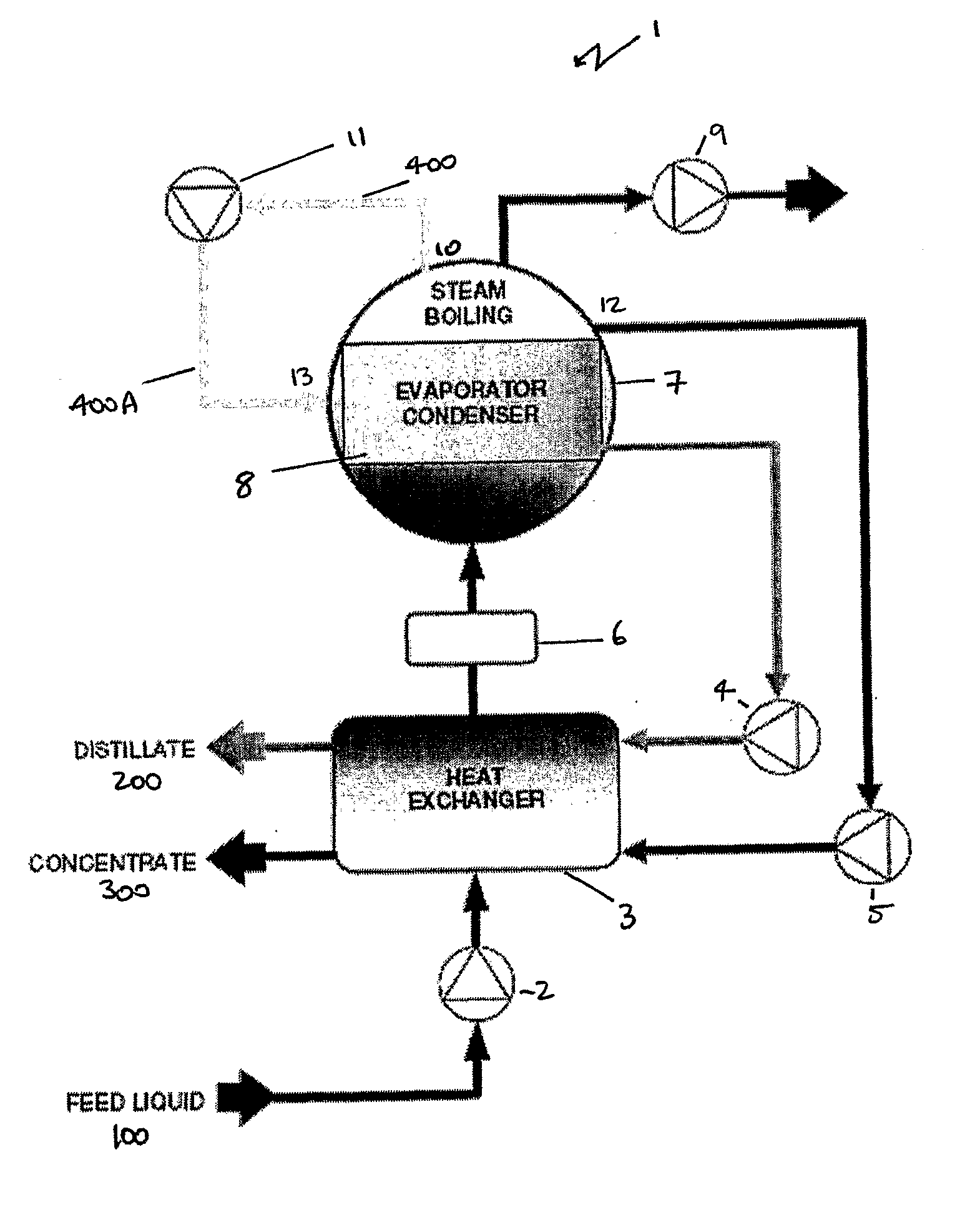
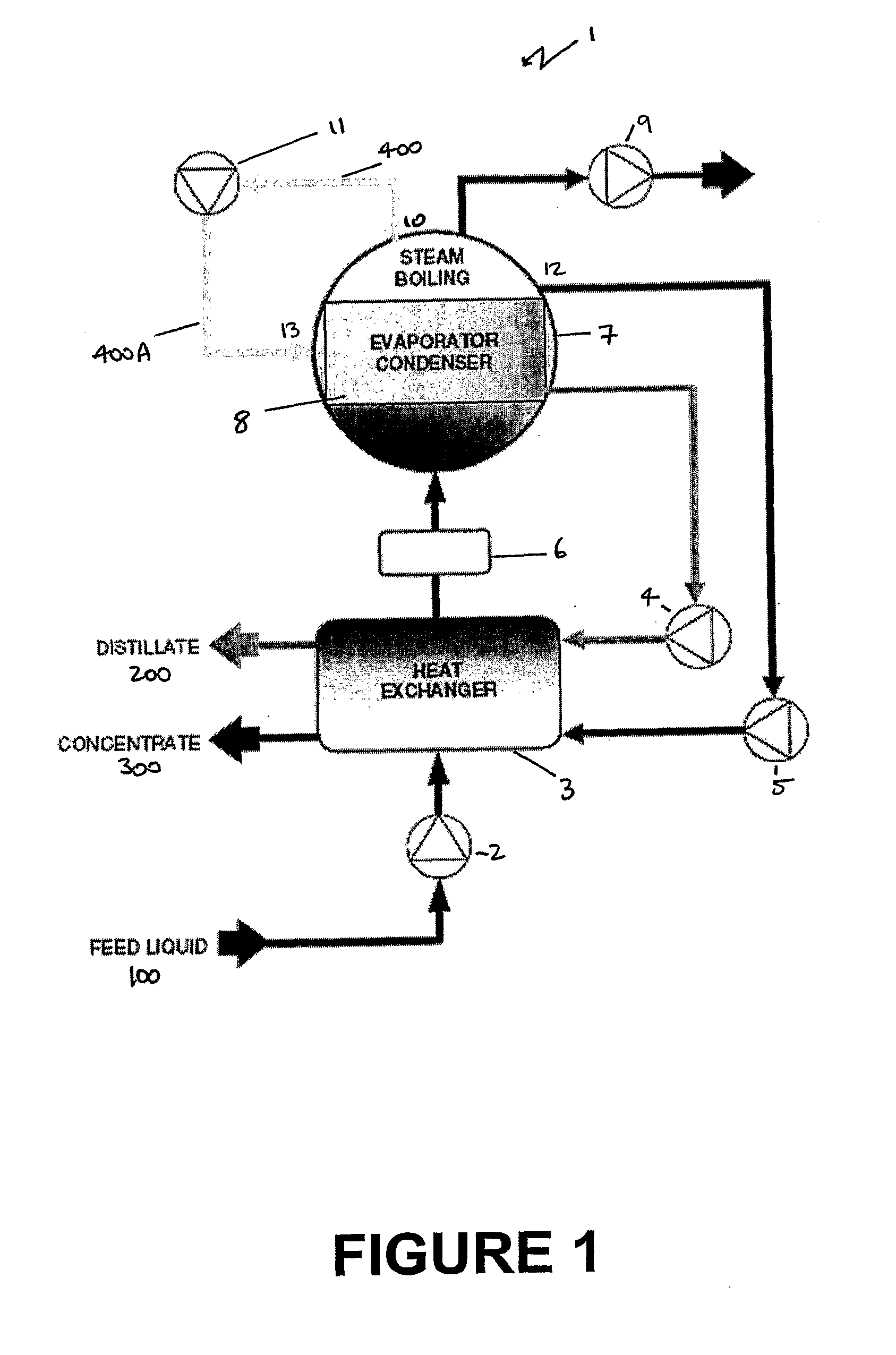
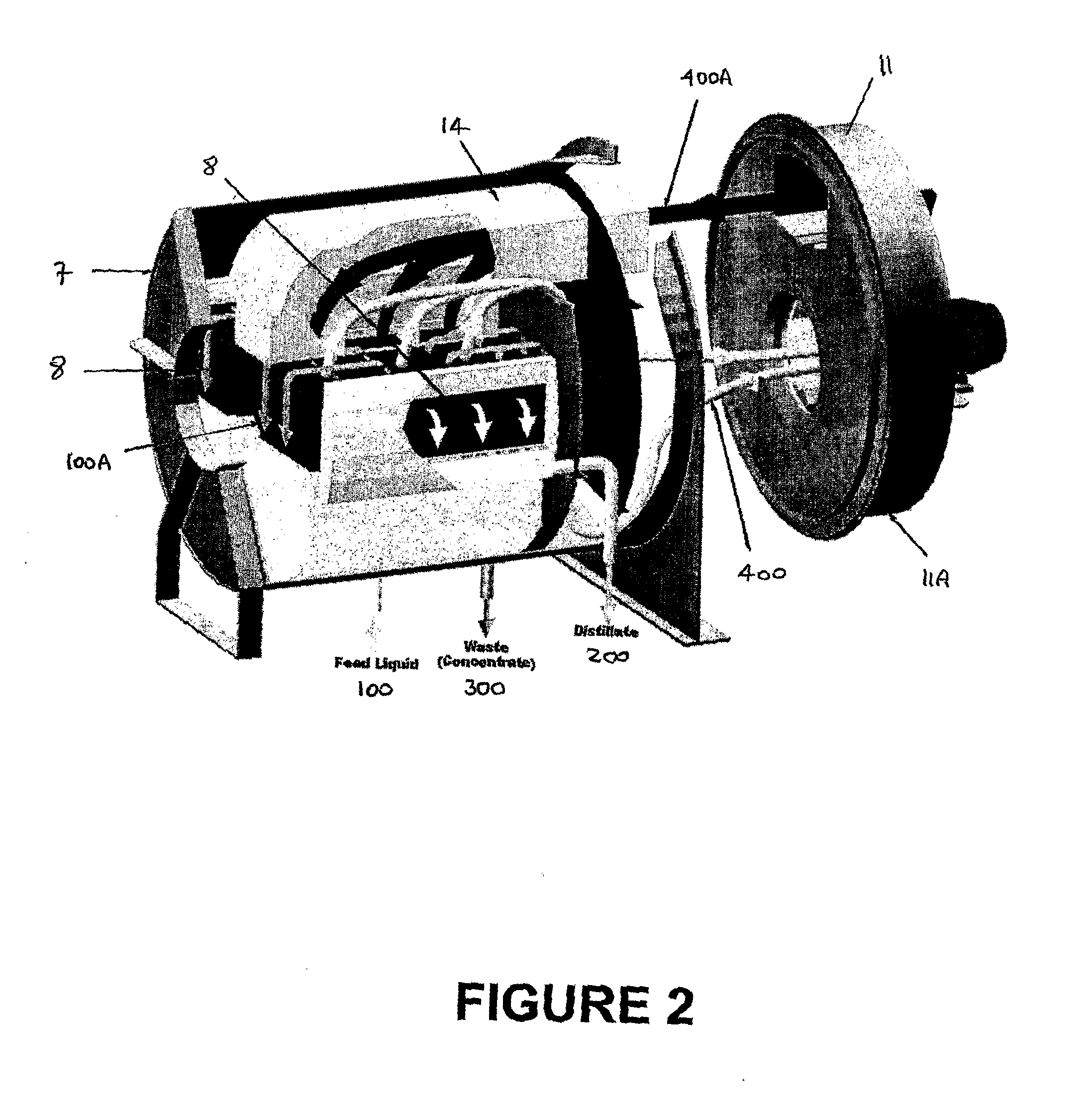
[0041]FIG. 1 shows a schematic view of the distillation apparatus generally indicated by arrow 1. Contaminated liquid 100 is pumped by feed pump 2 and preheated on passing through a heat exchanger 3, which recovers heat from the two output liquid streams: pure distilled water 200 pumped from distillate pump 4 and concentrated residues 300 pumped at contaminant pump 5. Heated to within a few degrees of boiling temperature, the liquid 100 next passes through a start-up heater 6, then enters vacuum chamber 7 containing evaporator / condenser unit 8 comprising a plurality of dynamic film thermal plates (not shown). A vacuum pump 9 attached to a vacuum chamber 7 produces a vacuum to be attached inside the chamber 7. The liquid 100 boils as it passes through the evaporator condenser unit 8, and the water vapor is drawn off at 10 by a vapor compressor 11. The remaining concentrated contaminant liquid 300 flows out of the chamber 7 at point 12, carrying away all contaminants.

[0042]The pure wa...


PUM

PropertyMeasurementUnit
Temperatureaaaaaaaaaa
Thicknessaaaaaaaaaa

Abstract

A modular distillation apparatus including at least one heat exchanger that preheats contaminated liquids; a heater that heats the contaminated liquid from the heat exchanger; an evaporator condenser adapted to boil the contaminated liquid coming out of the heater to produce water vapor and contaminant concentrate, and condense the water vapor into distilled water; a vacuum chamber capable of operating at below atmospheric pressure, the vacuum chamber housing the evaporator condenser and including at least one partition to separate the distilled water from the contaminant concentrate; a vapor compressor operably associated with the vacuum chamber to receive water vapor from the evaporator condenser in the vacuum chamber and pump the water vapor at pressure back through the evaporator condenser, wherein the heat exchanger recovers sensible heat from outgoing condensed distilled water and contaminant concentrate recycled from the vacuum chamber.

Description

STATEMENT OF CORRESPONDING APPLICATIONS[0001]This application is based on the Provisional specification filed in relation to U.S. Patent Application No. 60 / 913,731, the entire contents of which are incorporated herein by reference.TECHNICAL FIELD[0002]The present invention relates to a distillation apparatus. In particular the present invention relates to a distillation apparatus capable of producing distilled water from contaminated liquids using heat distillation under a vacuum and including recycling of latent and sensible heat within the apparatus to improve energy efficiency.BACKGROUND ART[0003]Traditionally liquid distillation systems, such as those used in desalination, ground water remediation or liquid recycling plants, have high energy requirements which can account for between 50% and 70% of the total operating costs of such a plant. These high operating costs can make such plants prohibitively expensive and impractical, particularly for applications in developing countri...

Claims


Application Information

Patent Timeline
IPC IPC(8): B01D3/10B01D3/00C02F1/04C02F1/08
CPCB01D1/28B01D1/2887F28D2021/0061C02F1/041C02F1/18B01D5/006F28F2265/18Y02P70/10Y02A20/00B01D1/221C02F2103/08
Inventor WARD, DUDLEY EDGAR JAMES
Owner EQUUS ENVIRONMENTAL
Learn More