Endoscope device and method for driving endoscope device

a technology of endoscope and endoscope, which is applied in the direction of picture signal generators, applications, television systems, etc., can solve the problems of deteriorating image quality, sensitivity cannot be avoided, and time of each pixel needs to be shortened, so as to prevent color divergence and improve image quality

Inactive Publication Date: 2010-08-12
FUJIFILM CORP
View PDF0 Cites 55 Cited by
  • Summary
  • Abstract
  • Description
  • Claims
  • Application Information

AI Technical Summary

Benefits of technology

[0009]The present invention is proposed by considering the above-described circumstances and it is an object of the present invention to provide an endoscope device that may prevent a color divergence and improve an image quality and a method for driving the endoscope device.
[0014]According to the present invention, an endoscope device that may prevent a color divergence and improve an image quality and a method for driving the endoscope device may be provided.

Problems solved by technology

Thus, there is a fear that the object to be shot or recorded may move with high possibility during this period and a color divergence may occur to deteriorate an image quality.
However, when a signal reading operation is carried out at high speed, an exposure time of each pixel needs to be shortened, so that the deterioration of sensitivity cannot be avoided.
Further, in accordance with the high-speed operation, a quantity of heat generation of an element itself is undesirably increased.

Method used


Image

  • Endoscope device and method for driving endoscope device
  • Endoscope device and method for driving endoscope device
  • Endoscope device and method for driving endoscope device

Examples


first modified example

[0130]An endoscope device of a first modified example has the same structure as that of the endoscope device shown in FIG. 1 and only an operation thereof is different from the endoscope device shown in FIG. 1. Now, the operation will be described below.

[0131]FIG. 8 is a timing chart for explaining an operation of the first modified example. FIG. 9 is a schematic diagram for explaining an operation of the first modified example. In FIG. 9, four pixel parts of 2 rows×2 columns in total are schematically shown.

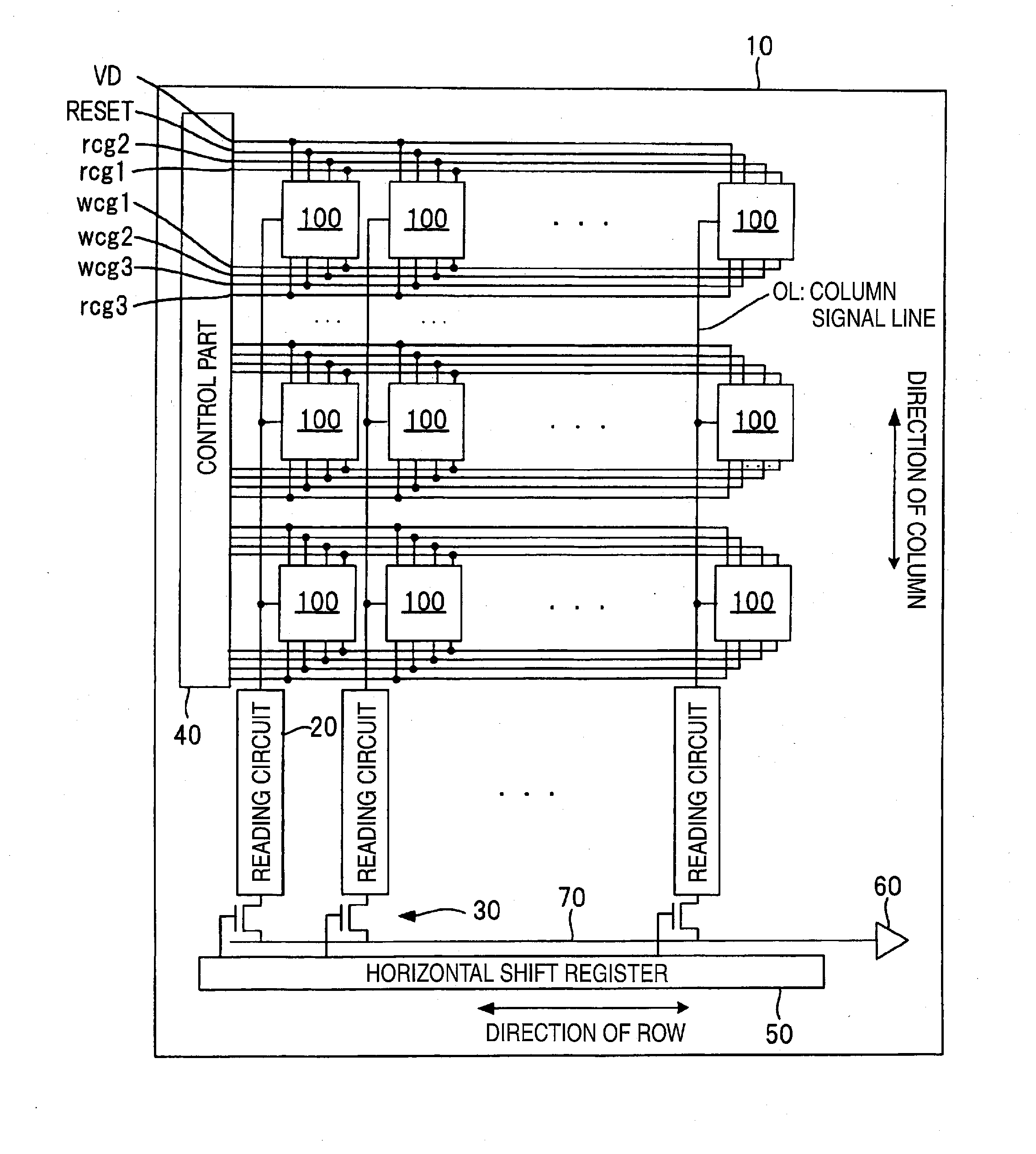
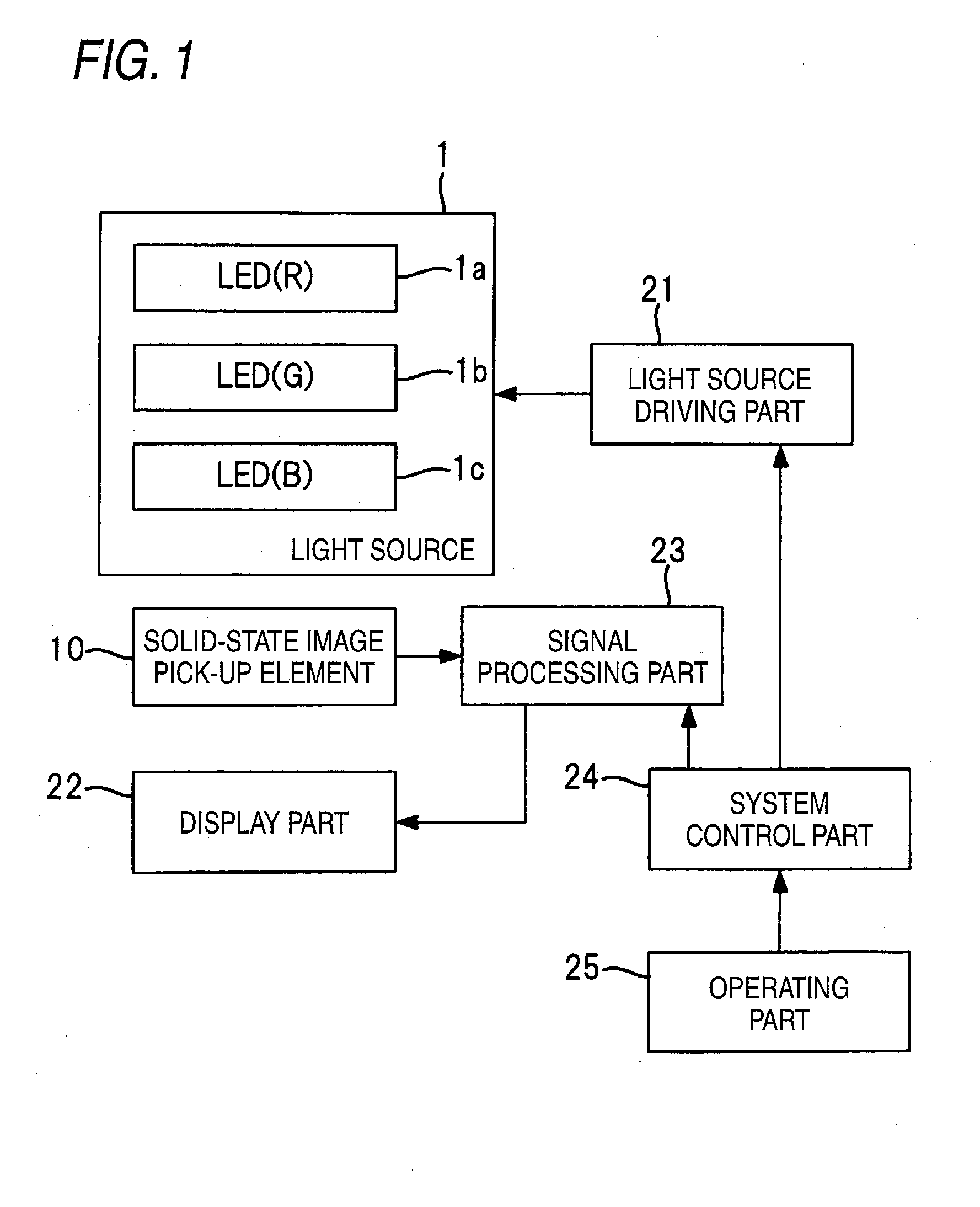
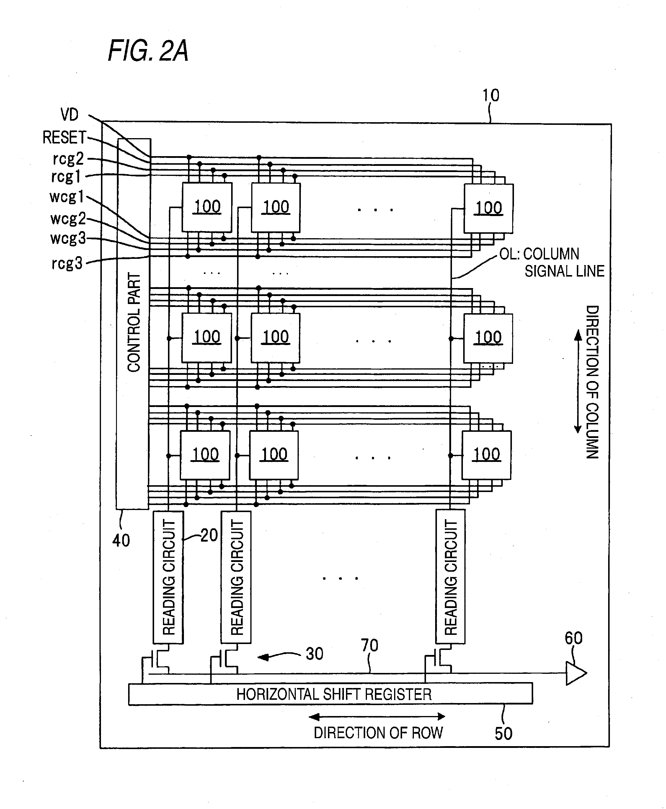
[0132]When an operating part 25 is operated to instruct an object to be shot or recorded, this instruction is inputted to a system control part 24 and the system control part 24 informs a solid-state image pick-up element 10 of the instruction for shooting or recording the object.

[0133]When the solid-state image pick-up element 10 receives the instruction for shooting or recording the object, a control part 40 considers it as a start trigger to supply reset pulses to reset gates...

second modified example

[0155]FIG. 10 is a diagram showing a schematic structure of an endoscope device of a second modified example. The endoscope device shown in FIG. 10 has a structure in which an LED 1d for emitting a special light 1 is added to the light source 1 of the endoscope device shown in FIG. 1.

[0156]The special light 1 is a light necessary for a person to identify biological information that cannot be identified by RGB lights (white color light). For instance, as shown in FIG. 11, the special light 1 has a light including a bright line in a specific wavelength located outside the wavelength areas of the R light, the G light and the B light. The specific wavelength of the special light 1 may be arbitrarily determined depending on biological information desired to be observed. Various kinds of wavelengths may be set, for instance, a wavelength for lighting an object to definitely recognize whether or not a red color (hemoglobin) appears, a wavelength for lighting an object to definitely recogni...

third modified example

[0189]FIG. 14 is a diagram showing a schematic structure of an endoscope device of a third modified example. The endoscope device shown in FIG. 14 has a structure in which an LED 1e for emitting a special light 2 is added to the light source 1 of the endoscope device shown in FIG. 10.

[0190]The special light 2 is a light necessary for a person to identify a part that cannot be identified by RGB lights (white color light) like the special light 1. For instance, as shown in FIG. 11, the special light 2 is a light including a bright line in a specific wavelength located within the wavelength areas of a G light. The specific wavelength of the special light 2 may be arbitrarily determined depending on biological information desired to be observed like the special light 1. However, the special light 2 has the bright line in the wavelength different from that of the special light 1.

[0191]FIG. 15 is a timing chart for explaining the operation of the endoscope device of the third modified exa...


PUM


Abstract

An endoscope device includes: a light source including an LED for emitting an R light, an LED for emitting a G light and an LED for emitting a B light, and a solid-state image pick-up element having a plurality of pixel parts including a photoelectric conversion part that may receive the R light, the G light and the B light to generate electric charges corresponding to the received lights and floating gates that may selectively store the electric charges generated in the photoelectric conversion part and a reading circuit that independently reads signals corresponding to the electric charges respectively stored in the floating gates.

Description

CROSS-REFERENCE TO RELATED APPLICATION[0001]This application is based on and claims priority under 35 USC 119 from Japanese Patent Application No. 2009-019949 filed on Jan. 30, 2009 and Japanese Patent Application No. 2009-127952 filed on May 27, 2009.BACKGROUND[0002]1. Technical Field[0003]The present invention relates to an endoscope device provided with a solid-state image pick-up element having a plurality of pixel parts and a method for driving the endoscope device.[0004]2. Related Art[0005]An electronic endoscope device includes a surface sequential system in which an object is lighted sequentially by the lights of colors of R (red color), G(green color) and B(blue color) respectively and the lights from the object are received by a solid-state image pick-up element having no color filter to carry out a shooting operation or an image recording operation and a surface simultaneous system in which an object is lighted by a white color light and the lights from the object are rec...

Claims


Application Information

Patent Timeline
Patent Type & Authority Applications(United States)
IPC IPC(8): H04N7/18A61B1/04
CPCA61B1/045A61B1/05A61B1/0638A61B1/0676A61B1/0684A61B2562/0233H04N2209/043H01L27/14603H01L27/14609H04N5/2256H04N5/37452H04N9/045H04N2005/2255A61B2562/046H01L27/14614A61B1/0655H04N23/555H04N23/56H04N25/771H04N23/84
Inventor SHIZUKUISHI, MAKOTOHATORI, MASAMIISHIMARU, YOSHIAKI
Owner FUJIFILM CORP
Why Eureka
Try Eureka