Microphone Unit

a microphone unit and microphone technology, applied in the field of microphone units, can solve the problems of reducing the size affecting the quality of the microphone unit, so as to achieve stable characteristics, accurately mount, and manufacture the microphone unit with the desired characteristics

Active Publication Date: 2010-08-12
TAIWAN SEMICON MFG CO LTD
View PDF3 Cites 27 Cited by
  • Summary
  • Abstract
  • Description
  • Claims
  • Application Information

AI Technical Summary

Benefits of technology

[0021]In the microphone unit configured as described above, the electroacoustic conversion portion may be a MEMS (micro electro mechanical system) chip. Thus, it is possible to manufacture a high-performance and small microphone unit having stable characteristics.
[0022]According to the present invention, it is possible to provide the microphone...

Problems solved by technology

However, since the size of microphone units tends to be reduced partly because electronic devices tend to be decreased in size, even when the position of the MEMS chip 102 is adjusted with the MEMS chip 102 observed with a CCD camera or...

Method used


Image

  • Microphone Unit
  • Microphone Unit
  • Microphone Unit

Examples


Embodiment Construction

[0032]An embodiment of a microphone unit according to the present invention will be described in detail below with reference to the accompanying drawings.

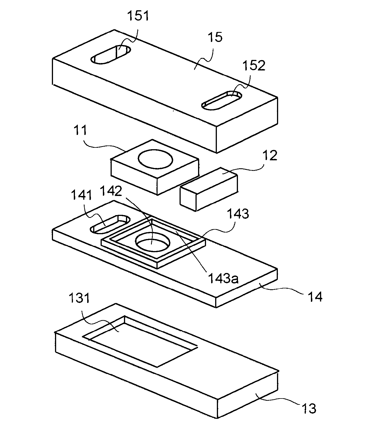
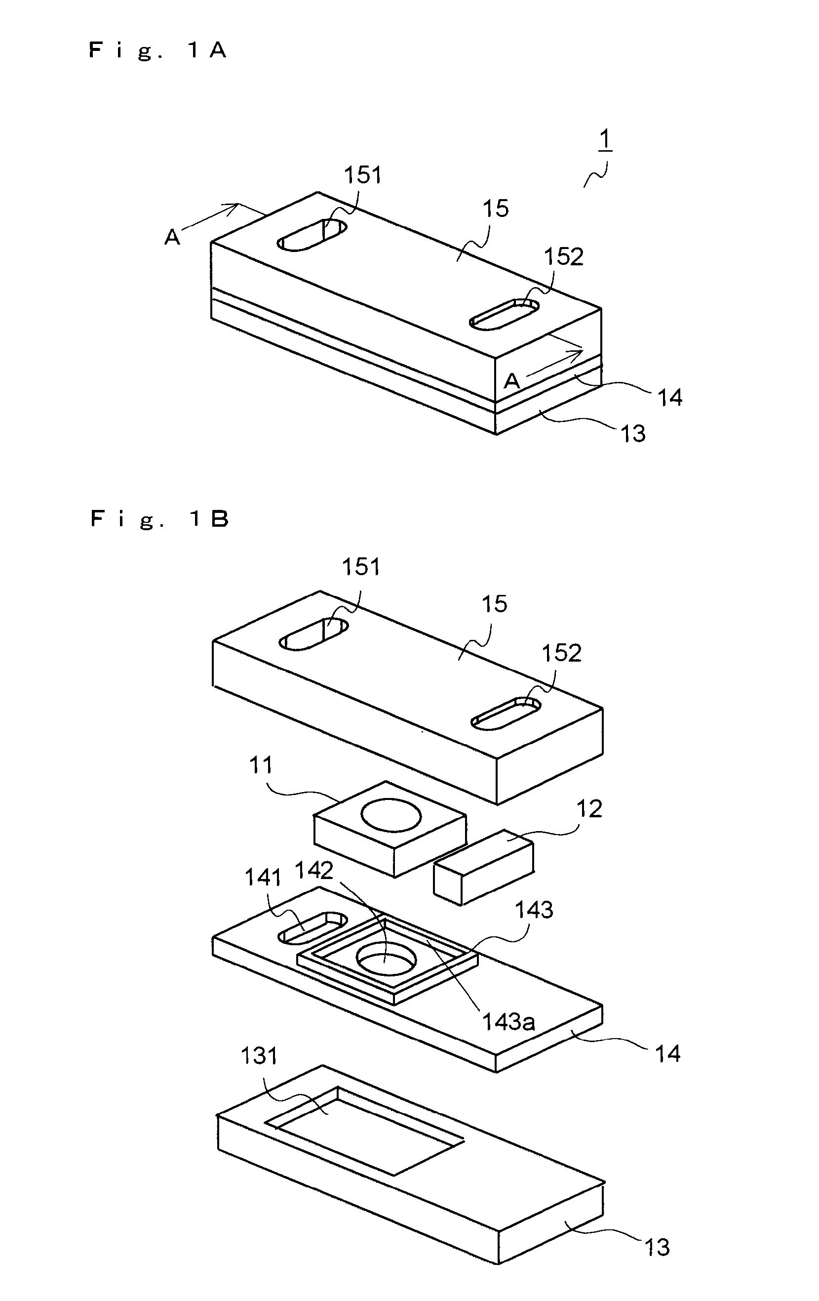
[0033]FIG. 1A is a schematic perspective view showing the configuration of the microphone unit of this embodiment. FIG. 1B is an exploded perspective view showing the configuration of the microphone unit of this embodiment. FIG. 2 is a schematic cross-sectional view taken along position A-A of FIG. 1A.

[0034]As shown in FIGS. 1A, 1B and 2, the microphone unit 1 of this embodiment is provided with a MEMS (micro electro mechanical system) chip 11, an ASIC (application specific integrated circuit) 12, a first board 13, a second board 14 and a cover portion 15.

[0035]The MEMS chip 11 is an embodiment of an electroacoustic conversion portion that converts a sound pressure into electrical signals, and is formed with a condenser microphone. The MEMS chip 11 is formed with a silicon chip, and includes, as shown in FIG. 2, an insulation base ...


PUM


Abstract

A microphone unit is provided with an electroacoustic conversion portion that includes a diaphragm vibrated by sound pressure and that converts the sound pressure into electrical signals and a board on which the electroacoustic conversion portion is mounted. In the board, there are provided a board opening portion that is formed to face the diaphragm and locating walls that come in contact with the electroacoustic conversion portion to locate the electroacoustic conversion portion.

Description

[0001]This application is based on Japanese Patent Application No. 2009-28387 filed on Feb. 10, 2009, the contents of which are hereby incorporated by reference.BACKGROUND OF THE INVENTION[0002]1. Field of the Invention[0003]The present invention relates to a microphone unit that converts a sound pressure (generated such as by voice) into electrical signals and outputs the resulting signals.[0004]2. Description of Related Art[0005]Conventionally, microphone units are applied to voice input devices, examples of which are sound communication devices such as mobile telephones and transceivers, information processing systems, such as voice authentication systems, that utilize a technology for analyzing input voice and recording devices. Conventionally, as these microphone units, microphone units having various configurations are developed (for example, see patent document 1).[0006]FIG. 6 is a schematic cross-sectional view showing an example of the configuration of a conventional microp...

Claims


Application Information

Patent Timeline
IPC IPC(8): H04R19/04
CPCH04R1/021H04R1/08H01L2924/1461H01L2924/3025H01L2924/10253H01L2224/48137H01L2224/48091H04R2201/003H04R19/04H01L2924/00014H01L2924/00
Inventor INODA, TAKESHIHORIBE, RYUSUKETANAKA, FUMINORI
Owner TAIWAN SEMICON MFG CO LTD
Why Eureka
Try Eureka