

Fuel cell system with regeneration of electrode activity during start or stop
a fuel cell and electrode activity technology, applied in the field of fuel cell systems, can solve the problem of not achieving effective performance recovery of fuel electrodes
- Summary
- Abstract
- Description
- Claims
- Application Information
AI Technical Summary
Benefits of technology
Problems solved by technology
Method used
Image

Examples
first embodiment
[0030]An embodiment of a fuel cell system provides a function to recover the performance of fuel cells that have deteriorated, particularly to recover the performance of deteriorated fuel electrode catalyst layers. Preferably, the fuel cell system includes a stack of polymer electrolyte fuel cells.
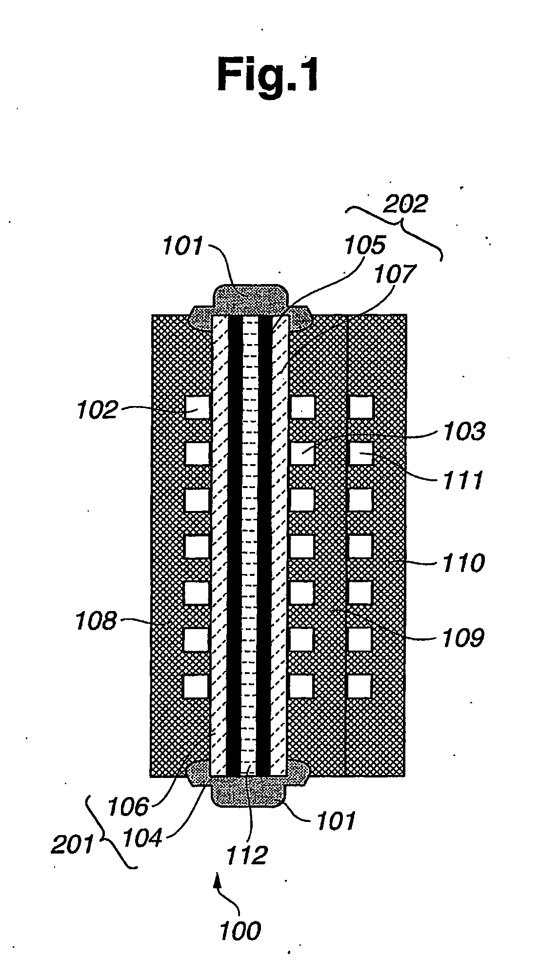
[0031]As shown in FIG. 1, an individual fuel cell provides a power generator unit 100. Preferably, power generator unit 100 (also called a “cell unit”) includes a polymer electrolyte membrane 112, a fuel electrode 201 (also called a “fuel gas diffusion electrode”), an oxidizing electrode 202 (also called an “oxidizing gas diffusion electrode”), a fuel gas separator 108, an oxidizing gas separator 109, and a refrigerant separator 110. The separators may also be referred to respectively as “separator plates.”
[0032]As shown in FIG. 1, fuel electrode 201 and oxidizing electrode 202 are arranged on opposite sides or surfaces of polymer electrolyte membrane 112. That is, polymer electrolyte memb...
second embodiment
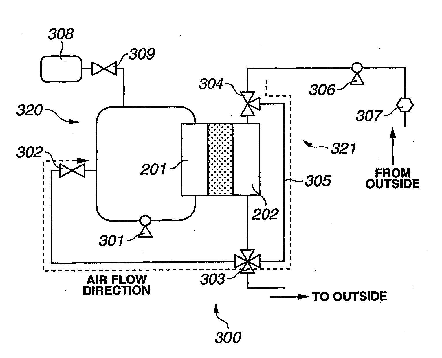
[0075]A second embodiment of a fuel cell system will now be described with reference to the exemplary embodiment of the gas piping system illustrated in FIG. 4 and the method depicted in FIG. 11.
[0076]The flowchart shown in FIG. 11 includes operation steps S11 to S22. Generally, operation steps S11 to S18 correspond to operation steps S1 to S8 shown in FIG. 10, and therefore an explanation thereof will not be repeated. As in the first embodiment, air is introduced to fuel electrode 201 and fuel electrode 201 is kept at a higher potential for a predetermined time.
[0077]At step S19 of FIG. 11, fuel gas purge valve 302 of FIG. 4 is closed. At step S20, fuel gas supply valve 309 is opened to supply fuel gas (e.g., hydrogen) from fuel gas supply source 308 to fuel electrode 201, thereby producing water by reacting with oxygen that remains in fuel electrode 201. At step S21, a check is carried out as to whether or not the fuel cell voltage is stable at or near zero volts. If the voltage i...
third embodiment
[0080]A third embodiment of a fuel cell system will now be described with reference to the exemplary embodiment of the gas piping system illustrated in FIG. 4 and the method depicted in FIG. 12.
[0081]The flowchart shown in FIG. 12 includes operation steps S21 to S30. Generally, operation steps S21 to S28 correspond to operation steps S1 to S8 shown in FIG. 10, and an explanation thereof will not be repeated. Again, as in the first embodiment, air is introduced to fuel electrode 201 and fuel electrode 201 is kept at a higher potential for a predetermined time.
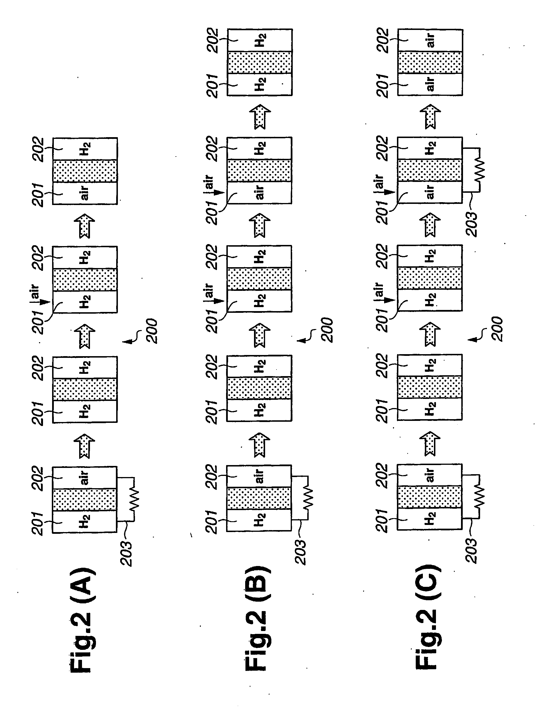
[0082]At step S29 of FIG. 12, hydrogen is consumed in the fuel cell and air is supplied to fuel electrode 201. Then, both fuel and oxidizing electrodes 201, 202 are stopped in air atmosphere. Hydrogen is consumed when electricity is produced or when both electrodes are electrically shorted. A reaction with the hydrogen remaining in oxidizing electrode 202 may produce water on the catalyst layer of the fuel electrode 201, and thu...
PUM
| Property | Measurement | Unit |
|---|---|---|
| voltage | aaaaa | aaaaa |
| voltage | aaaaa | aaaaa |
| voltage | aaaaa | aaaaa |
Abstract
Description
Claims
Application Information