Brake system for a motor vehicle

a technology for brake systems and motor vehicles, applied in brake systems, mechanical equipment, transportation and packaging, etc., can solve problems such as negative pressure over a prolonged period of time, and achieve the effect of satisfying requirements

Inactive Publication Date: 2010-08-19
CONTINENTAL TEVES AG & CO OHG
View PDF24 Cites 9 Cited by
  • Summary
  • Abstract
  • Description
  • Claims
  • Application Information

AI Technical Summary

Benefits of technology

[0011]An object of the present invention, is to create a brake system which, without unwanted volume losses for priming, under all ambient conditions ensures an adequate volume supply to the pump and which satisfies the requirements in terms of response time and manufacturing costs.

Problems solved by technology

This serves on the one hand to compensate rapidly for the change in volume and pressure and means that a functionally detrimental negative pressure over a prolonged period of time, which would lead to the escape of air dissolved in the hydraulic fluid, is not generated in the first place.

Method used


Image

  • Brake system for a motor vehicle
  • Brake system for a motor vehicle
  • Brake system for a motor vehicle

Examples


Embodiment Construction

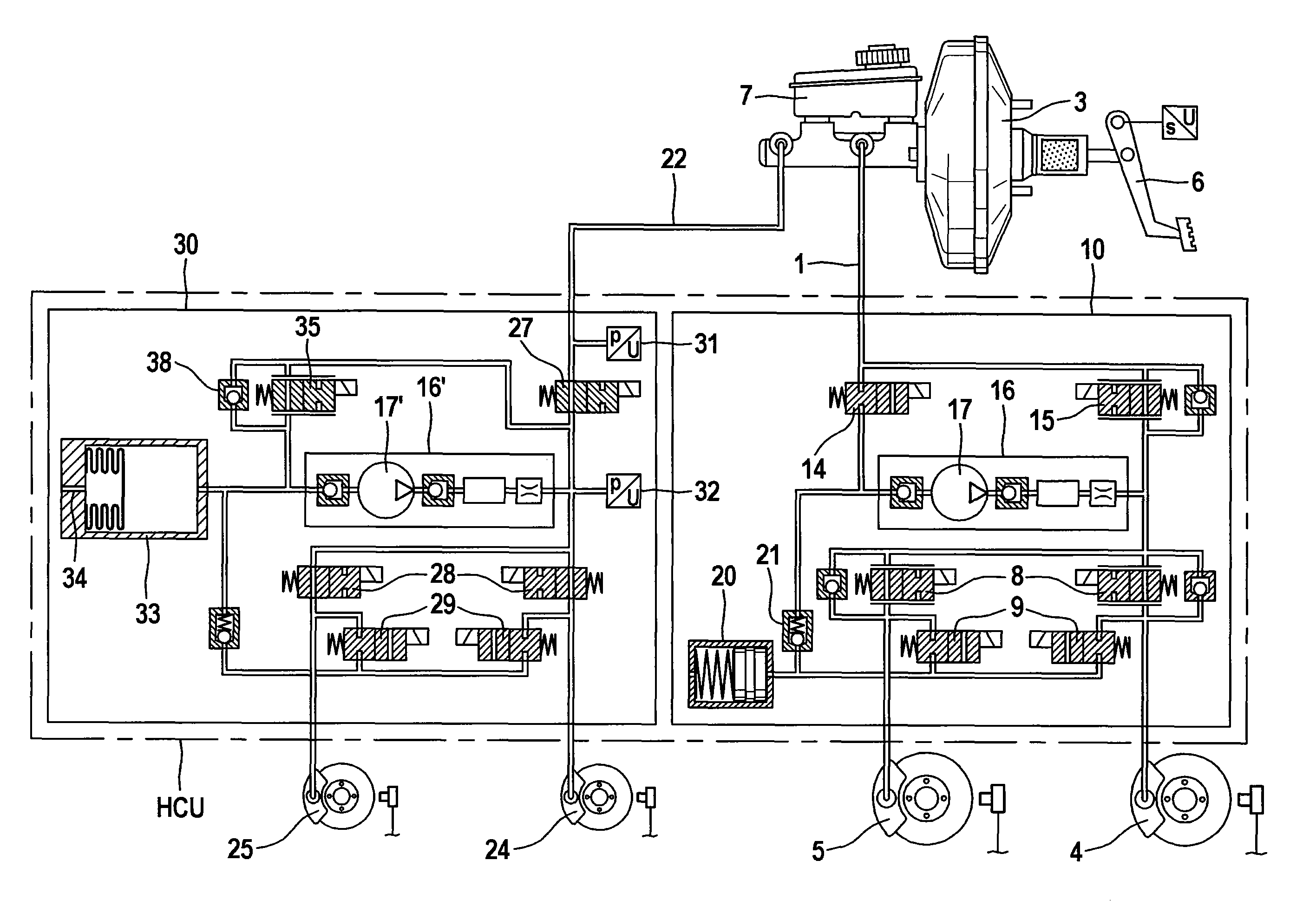
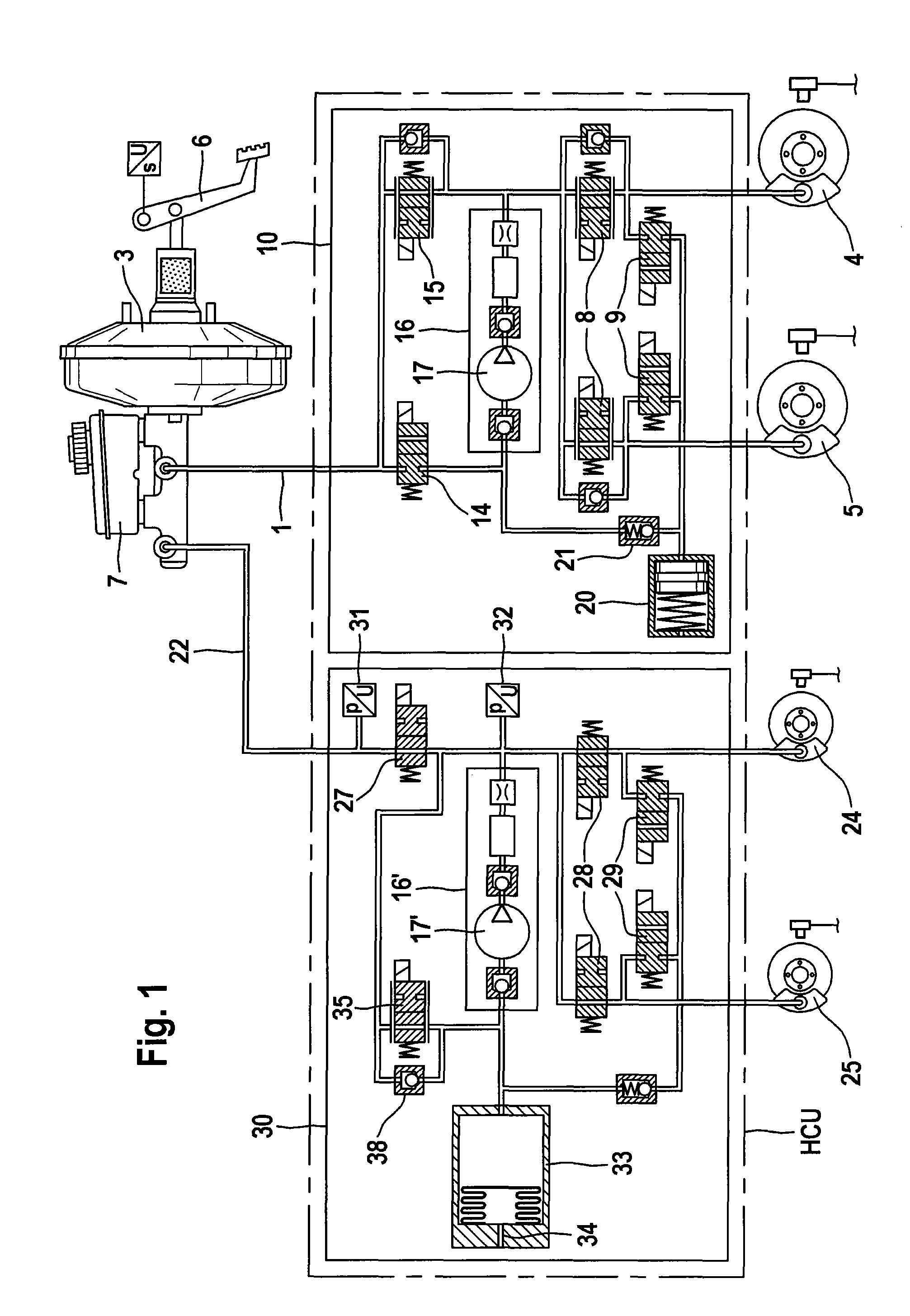
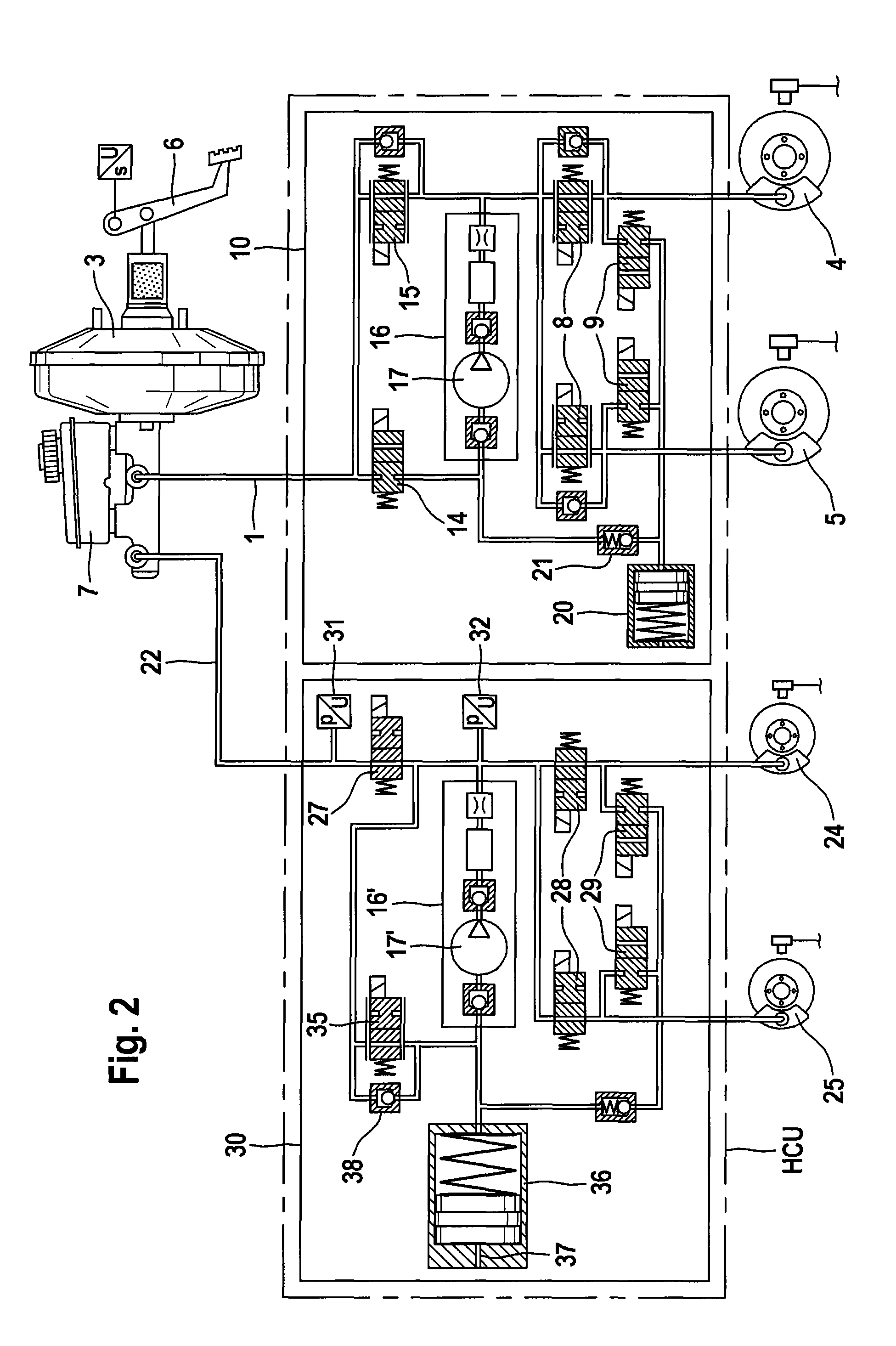
[0028]The brake system shown in FIG. 1 is a brake system which in addition to four friction brakes 4, 5, 24, 25 also comprises an electrical alternator (not shown) for generating electrical energy and as a regenerative brake. The brake system is preferably designed so that a maximum possible brake torque will be applied via the electrical alternator, in order to achieve a high motor vehicle efficiency. Alternatively, instead of an alternator a flywheel mass accumulator or a hydraulic converter with hydraulic accumulator may be provided, which convert kinetic energy into potential energy in order to reuse this later to drive the motor vehicle.

[0029]The brake system is provided with a brake booster, which is designed as a tandem master cylinder 3, preferably power-assisted. The brake pressure applied by the tandem master cylinder 3 is transmitted to the friction brakes 4, 5, 24, 25 by a brake fluid via hydraulic lines 1, 22 and the hydraulic units 10 and 30. The hydraulic unit 10 acts...


PUM


Abstract

A brake system for a motor vehicle which simplifies the hydraulic design and avoids a vacuum prevailing over a relatively long period of time. The first hydraulic unit has a suction volume, which is connected to the suction side of the pump and which, in the event of a change in the pressure on the suction side of the pump, provides a pressure and volume equalization by means of the brake fluid stored in the suction volume, with an elastic element.

Description

CROSS REFERENCE TO RELATED APPLICATIONS[0001]This application is the U.S. national phase application of PCT International Application No. PCT / EP2008 / 061623, filed Sep. 3, 2008, which claims priority to German Patent Application No. 102007042204.2, filed Sep. 5, 2007, German Patent Application No. 102007042202.6, filed Sep. 5, 2007 and German Patent Application No. 102008039960.4, filed Aug. 27, 2008, the contents to such applications being incorporated by reference herein.BACKGROUND OF THE INVENTION[0002]The present invention relates to a brake system for a motor vehicle which has a brake pressure-generating means, with or without power-assistance, with a non-pressurized storage reservoir, the brake pressure-generating means being connected to a human-machine interface, which by way of a brake fluid serves for generating hydraulic brake pressure for brake devices, preferably friction brakes, the brake system providing at least a first hydraulic unit for connecting the brake pressure...

Claims


Application Information

Patent Timeline
Patent Type & Authority Applications(United States)
IPC IPC(8): B60T8/40B60L7/24B60T8/48B60T11/10
CPCB60L7/24B60T8/4881B60T8/4072B60T8/267
Inventor HITZEL, MICHAELJUNG, MICHAELHAUKE, BERNHARDKLEY, RONALDSCHMITT, STEFAN A.
Owner CONTINENTAL TEVES AG & CO OHG
Why Eureka
Try Eureka