Counter rotating fan design and variable blade row spacing optimization for low environmental impact

Active Publication Date: 2010-08-19
THE BOEING CO
View PDF13 Cites 63 Cited by
  • Summary
  • Abstract
  • Description
  • Claims
  • Application Information

AI Technical Summary

Benefits of technology

[0011]In a first exemplary embodiment, counter rotation transmission unit carries the inner blade row with the power shaft extending through and supported by the unit. One aspect of the embodiment includes a pitch control unit for the inner blade row and a pitch control unit for the outer blade row.
[0012]For one implementation of the exemplary embodiment, the outer blade row is upstream of the inner blade row in a tractor configuration and power supplied by the power shaft to the outer blade row is less than power supplied to the inner blade row by the counter rotation transmission unit with the outer blade row in the extended position. In one exemplary configuration, the ratio of power supplied to the outer blade row and inner blade row is substantially less than 1.0 during noise sensitive portions of the mission. This implementation further provides that the inner blade

Problems solved by technology

Furthermore, it is anticipated that local air-quality or other carbon related environmental costs could be imposed.
Improved fuel consumption may be obtained by reducing cruise speed however this may increase flight time and be undesirable to passengers, the net fuel benefit may be fairly small, challenges with air traffic integration may be created, the number of revenue flights in a given day might be reduced, and this approach may actually result in an increase of other airline operating costs.
Counter Rotating Open Fans have complex noise sources that single rotation turboprops do not have; specifically propeller wake interaction and tip vortex interaction noise.
Both of these noise sources may result in external environmental noise which affects airport communities, cabin noise which affects passenger comfort, and airplane structural sonic fatigue.
A high

Method used


Image

  • Counter rotating fan design and variable blade row spacing optimization for low environmental impact
  • Counter rotating fan design and variable blade row spacing optimization for low environmental impact
  • Counter rotating fan design and variable blade row spacing optimization for low environmental impact

Examples


Embodiment Construction

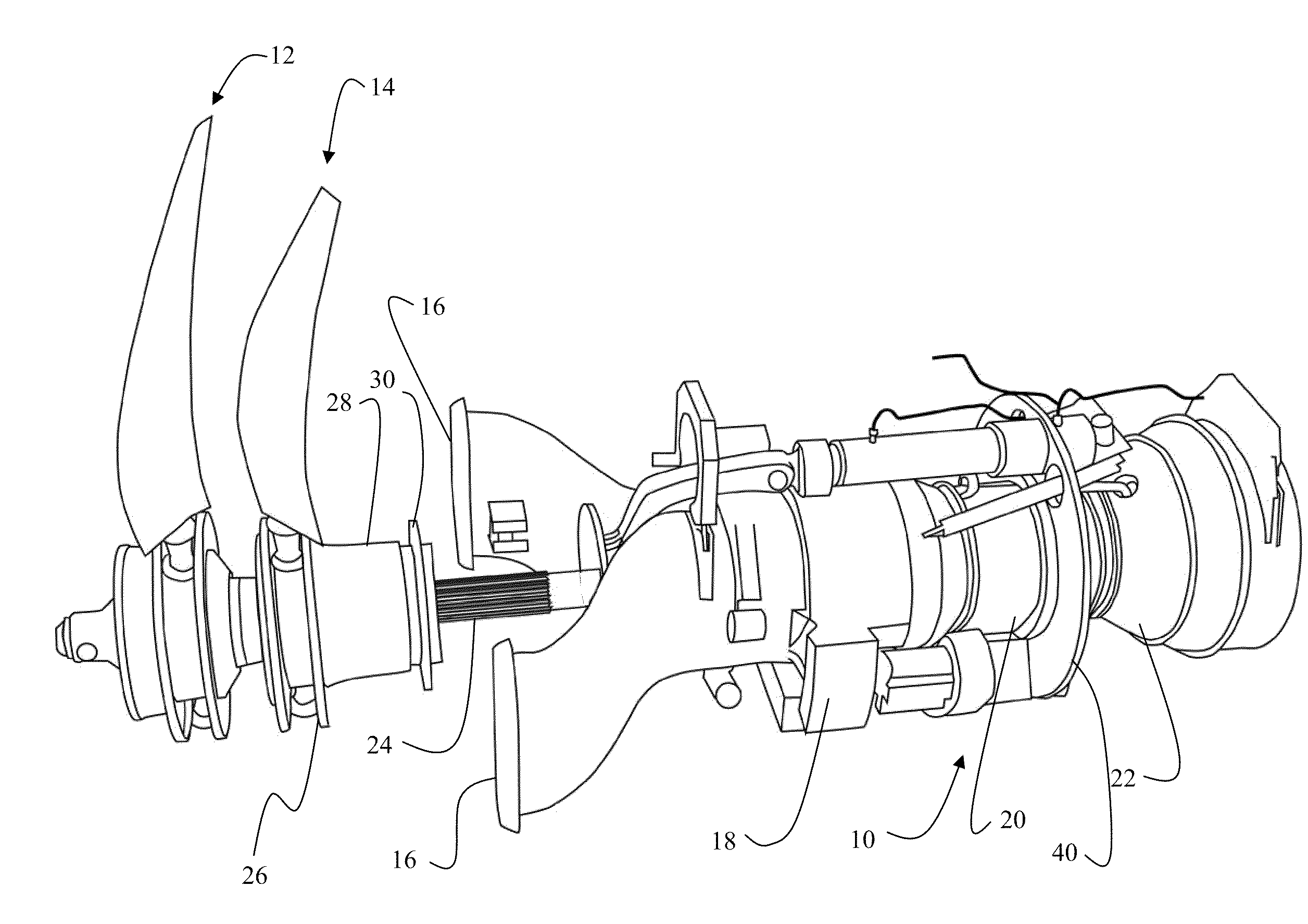
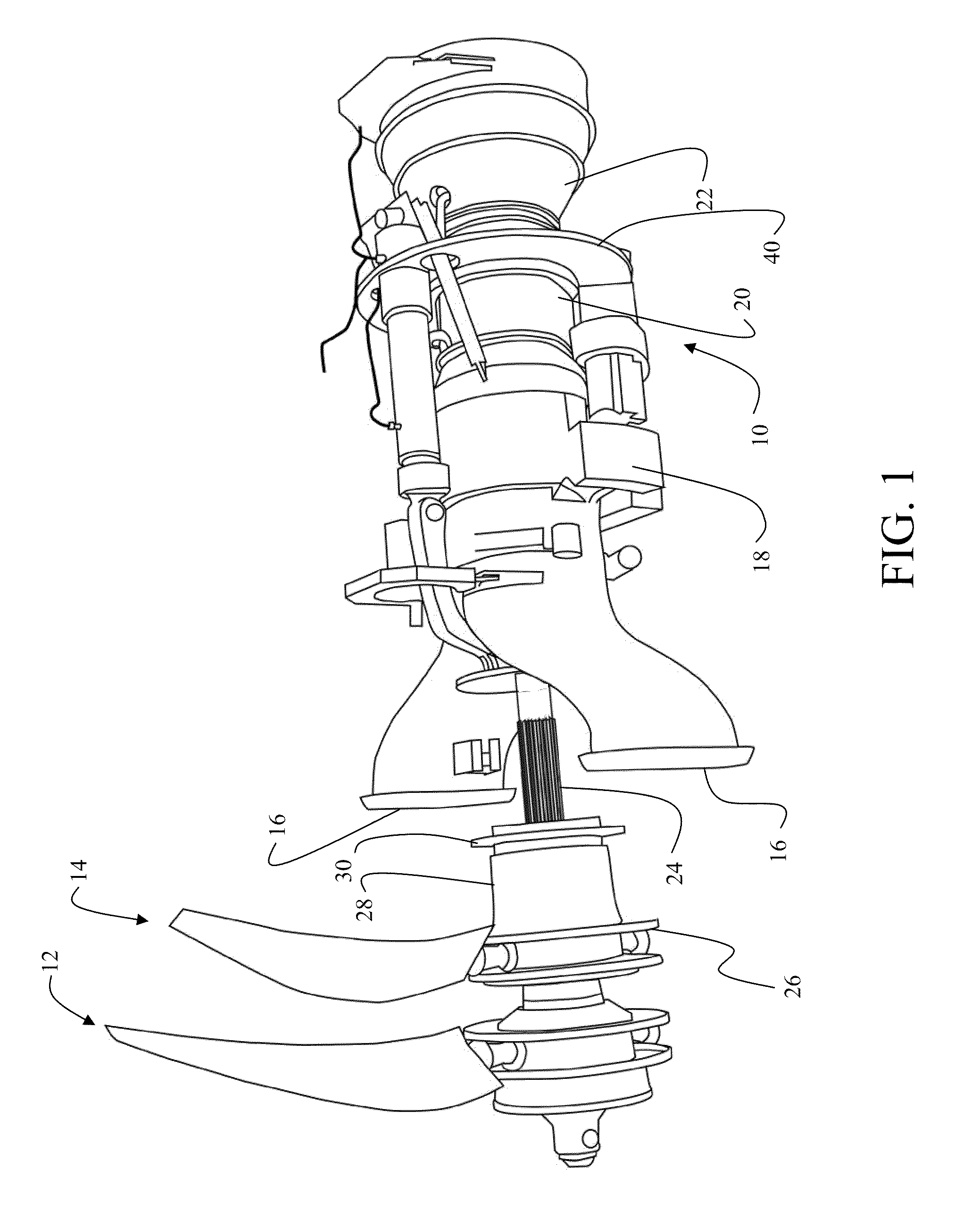
[0039]The embodiments disclosed herein provide counter rotating open fans (CROF) having adjustable positioning / spacing of adjacent airfoil blade rows during operation for real-time optimization of efficiency and noise in selected portions of the flight profile. A first embodiment shown in FIG. 1 employs a tractor configuration having an engine core 10 driving an outer upstream fan or blade row 12 and an inner downstream fan or blade row 14. For this embodiment, the upstream blade row has a larger diameter and is the outer row relative to the engine core and the downstream blade row is the inner row relative to the engine core and has a smaller diameter. For the descriptions herein, fan, blade row and rotor shall have substantially identical meaning. The engine core incorporates inlets 16 providing combustion air to a multistage compressor section 18 with a combustor 20 and a turbine section 22. Power to the blade rows 12 and 14 is provided through a shaft 24 driven by the turbine se...


PUM


Abstract

An air vehicle propulsion system incorporates an engine core with a power shaft to drive an outer blade row. The power shaft is extends through and is supported by a counter rotation transmission unit which drives an inner blade row in counter rotational motion to the outer blade row. The counter rotation transmission unit exchanges power from the engine core with the shaft. An actuator engages the shaft for translation from a first retracted position to a second extended position.

Description

BACKGROUND INFORMATION[0001]1. Field[0002]Embodiments of the disclosure relate generally to the field of propulsion systems for aircraft and more particularly to embodiments for a counter rotating fan with a variable blade row spacing.[0003]2. Background[0004]The escalating cost of aviation jet fuel, enactment of and anticipated growth in carbon-related taxation regulations has created an enthusiastic industry-wide resurgence into Prop-fan or Open-Fan technology, as demand for travel continues to climb with sustained pressure to minimize fare increases. Concurrently; due to increased travel the legal noise limits imposed by the United States Federal Aviation Administration (FAA) and the International (ICAO) agencies for engine and aircraft certification have become more stringent. In many countries, local aviation authorities have imposed a combination of fees, curfews, and quotas aimed to offset the growth of noise exposure and costs associated with abatement, including sound-proof...

Claims


Application Information

Patent Timeline
IPC IPC(8): B64D27/00F01D1/24
CPCB64C11/48F04D29/052B64D2027/026F02C3/107F02C7/36F02K3/025F02K3/072Y02T50/66F05D2270/44F05D2260/40311F05D2260/96F05D2260/57F05D2270/66F05D2220/90B64D35/06Y02T50/60
Inventor MOORE, MATTHEW D.BOREN, KELLY L.LANGTRY, ROBIN B.
Owner THE BOEING CO
Why Eureka
Try Eureka