Control system and control method for vehicle

a control system and control method technology, applied in electrical control, hybrid vehicles, exhaust treatment electric control, etc., can solve the problems of deterioration of exhaust emission characteristics, breakdown of sensors and catalysts, and abrupt drop in catalyst bed temperature, so as to prevent catalyst deactivation and acceleration performance enhancement

Inactive Publication Date: 2010-08-26
TOYOTA JIDOSHA KK
View PDF5 Cites 18 Cited by
  • Summary
  • Abstract
  • Description
  • Claims
  • Application Information

AI Technical Summary

Benefits of technology

[0006]The present invention provides a control system and control method for a vehicle which make it possible to achieve both prevention of catalyst deactivation and acceleration performance enhancement.

Problems solved by technology

However, in some cases, when the second exhaust valve is closed and only the first exhaust valve is opened in order to meet an acceleration request after completion of catalyst warm-up, this results in an abrupt drop in catalyst bed temperature.
In such cases, the catalyst becomes deactivated, which can lead to deterioration in exhaust emission characteristics.
In such cases, the sensor and the ceramic portion of the catalyst become damaged by water, which can cause breakdown of the sensor and the catalyst.

Method used


Image

  • Control system and control method for vehicle
  • Control system and control method for vehicle
  • Control system and control method for vehicle

Examples


embodiment 1

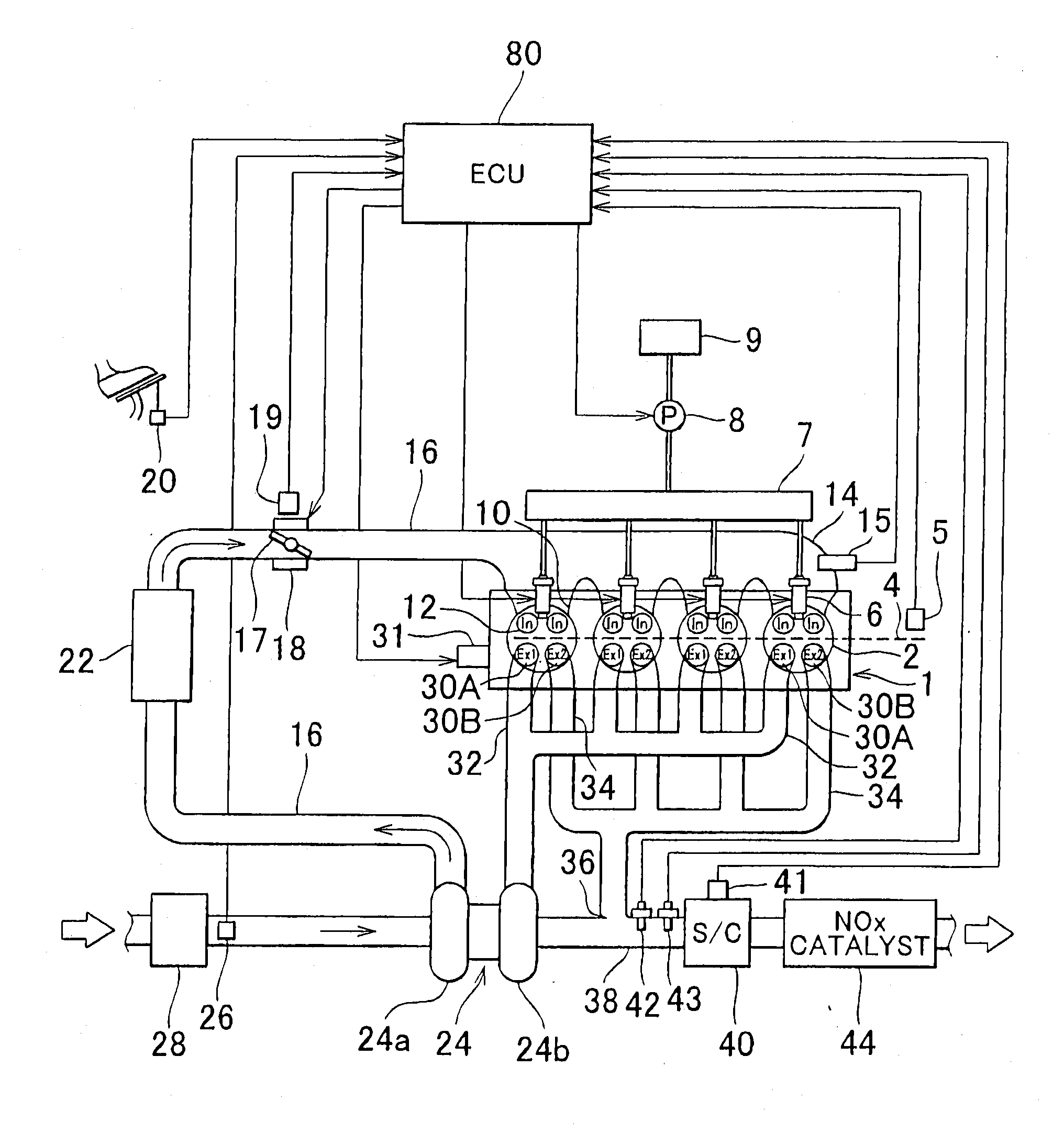
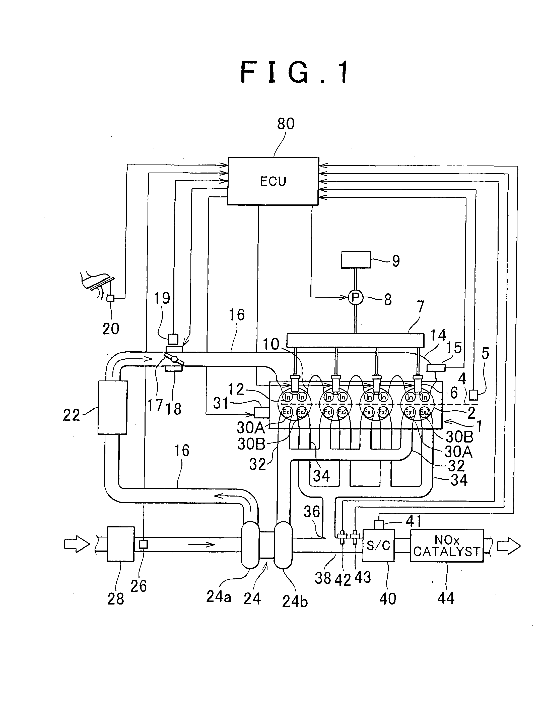
[0030]FIG. 1 is a diagram showing a system configuration of the present invention. A system according to this embodiment is an independent exhaust engine system having a turbocharger. The system shown in FIG. 1 includes an engine 1 having a plurality of cylinders 2. The engine 1 is mounted in a vehicle (not shown). The pistons of the cylinders 2 are each connected to a common crankshaft 4 via a crank mechanism. A crank angle sensor 5 that detects a crank angle CA is provided near the crankshaft 4.

[0031]The engine 1 has injectors 6 corresponding to the respective cylinders 2. The injectors 6 are configured to directly inject high-pressure fuel into the cylinders 2. The respective injectors 6 are connected to a common delivery pipe 7. The delivery pipe 7 communicates with a fuel tank 9 via a fuel pump 8.

[0032]Also, the engine 1 has intake ports 10 corresponding to the respective cylinders 2. The intake ports 10 are each provided with a plurality of intake valves 12 (sometimes accompa...

embodiment 2

[0073]Accordingly, in Embodiment 2, when the second exhaust valve Ex2 is opened to an intermediate lift as shown in FIG. 3B, the engine operating point is corrected to the high rotation side on the iso-output curve. More specifically, when the second exhaust valve Ex2 is opened to an intermediate lift, the engine operating point P1 on the iso-output curve L1 shown in FIG. 8 is corrected to an engine operating point P2. Since the engine speed NE is high at the engine operating point P2 relative to that at the engine operating point P1, the exhaust gas temperature Tex rises. Thus, exhaust energy supplied to the turbine 24b increases, so the turbo rpm increases, thereby making it possible to raise the boost pressure. As a result, even though the second exhaust valve Ex2 is opened to an intermediate lift, an output equivalent to that when the second exhaust valve Ex2 is fully closed can be obtained. Further, the warm-up of the first exhaust passage 32 and the turbine 24b can be promoted...


PUM


Abstract

A catalyst warm-up control is carried out in a state with a first exhaust valve closed and a second exhaust valve opened. After completion of the catalyst warm-up, if there is an acceleration request, exhaust gas temperature is acquired. If the exhaust gas temperature is equal to or lower than a predetermined value, the second exhaust valve is opened to an intermediate lift to thereby prevent an abrupt drop in exhaust gas temperature. If the exhaust gas temperature is higher than the predetermined value, the second exhaust valve is fully closed to thereby introduce the whole amount of exhaust gas to a turbine. A vehicle control device that achieves both prevention of catalyst deactivation and acceleration performance enhancement can be thus provided.

Description

BACKGROUND OF THE INVENTION[0001]1. Field of the Invention[0002]The present invention relates to a control system and control method for a vehicle having an internal combustion engine with a turbocharger. More specifically, the present invention relates to achieving both prevention of catalyst deactivation and acceleration performance enhancement.[0003]2. Description of the Related Art[0004]A device is known which includes a first exhaust valve that opens and closes a first exhaust passage leading to a turbine, and a second exhaust valve that opens and closes a second exhaust passage that does not pass through the turbine (independent exhaust engine) (see, for example, Japanese Patent Application Publication No. 10-89106 (JP-A-10-89106)). According to this device, by closing the first exhaust valve and opening the second exhaust valve, exhaust gas can be made to flow while bypassing the turbine, thereby achieving enhanced catalyst warm-up performance. After completion of the catalys...

Claims


Application Information

Patent Timeline
Patent Type & Authority Applications(United States)
IPC IPC(8): F02D23/00F01L1/34F01N3/10F01N9/00
CPCB60K6/442Y02T10/18B60L2240/445B60W2510/068B60W2540/10F01N13/107F02B37/02F02D13/0246F02D29/02F02D41/0007F02D41/1446F02D2041/001Y02T10/6234Y02T10/6239Y02T10/144B60K6/445Y02T10/12Y02T10/62
Inventor IRISAWA, YASUYUKI
Owner TOYOTA JIDOSHA KK
Why Eureka
Try Eureka