Arc Start Control Method

a control method and arc start technology, applied in the direction of arc welding apparatus, welding apparatus, manufacturing tools, etc., can solve the problems of deteriorating arc start performance, difficult to raise the arc accurately to a desirable value, and re-contact between wires and the base material, so as to reduce costs and simplify the structure of the whole circuit

Active Publication Date: 2010-08-26
DAIHEN CORP
View PDF1 Cites 18 Cited by
  • Summary
  • Abstract
  • Description
  • Claims
  • Application Information

AI Technical Summary

Benefits of technology

[0025]Accordingly, the state of the welding wire or the welding torch can be determined based on whether the state in which the welding voltage value before the short circuit determination has continued for a predetermined period or longer. In other words, same operatio...

Problems solved by technology

This is because if the slow-down feed speed is raised, physical contact between the welding wire and the base material causes the welding wire to be strongly pressed against the base material and deformed or lifts up the welding torch 4, so that the arc start performance is deteriorated.
This is because, if movement of the welding wire is switched from retract to advance immediately after the initial arc has been produced, the wire and the base material may be caused to re-contact with each other due to an insufficient arc length.
If the arc flares up when the welding wire is retracted, it is difficult to raise the arc accurat...

Method used


Image

  • Arc Start Control Method
  • Arc Start Control Method
  • Arc Start Control Method

Examples


first embodiment

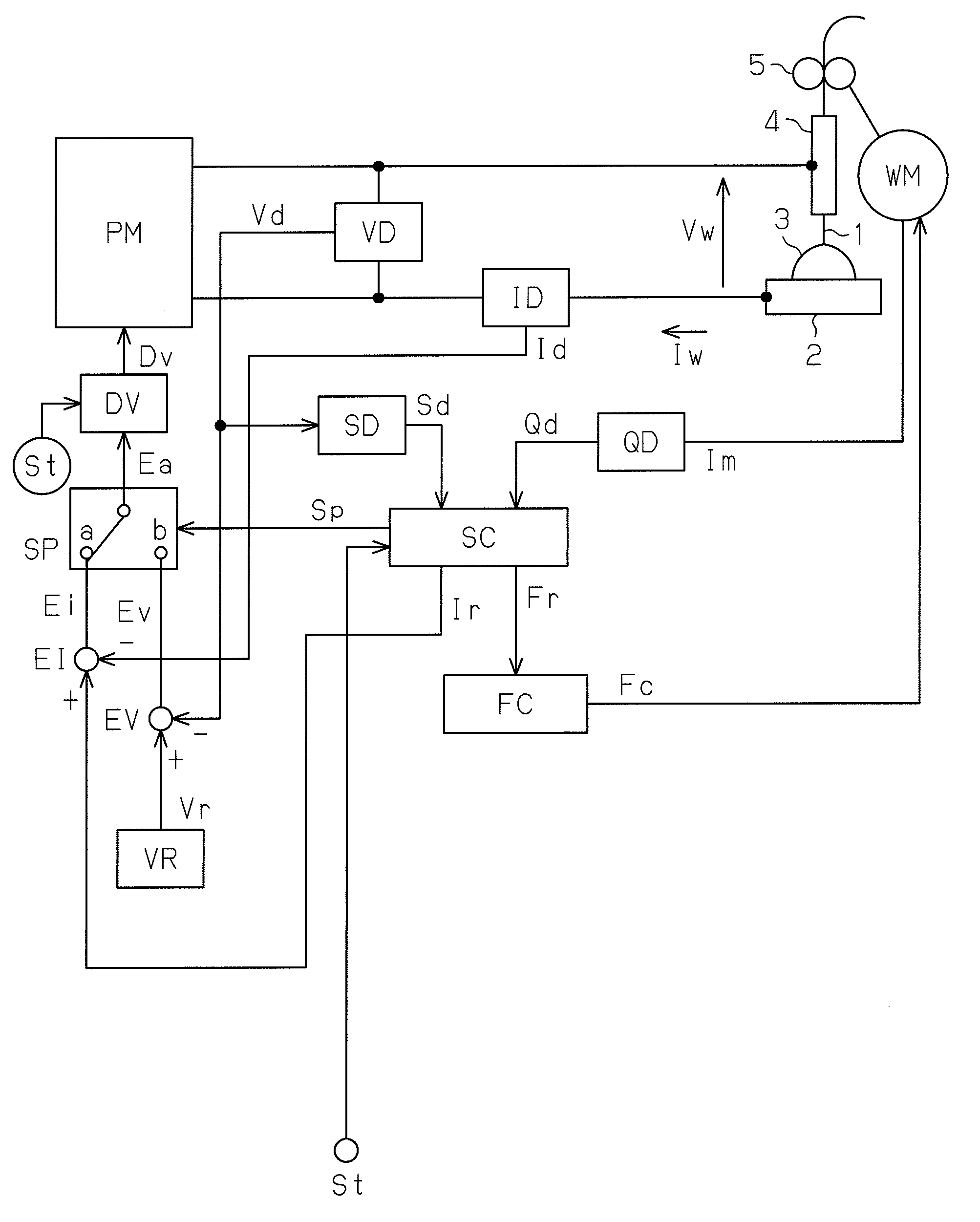
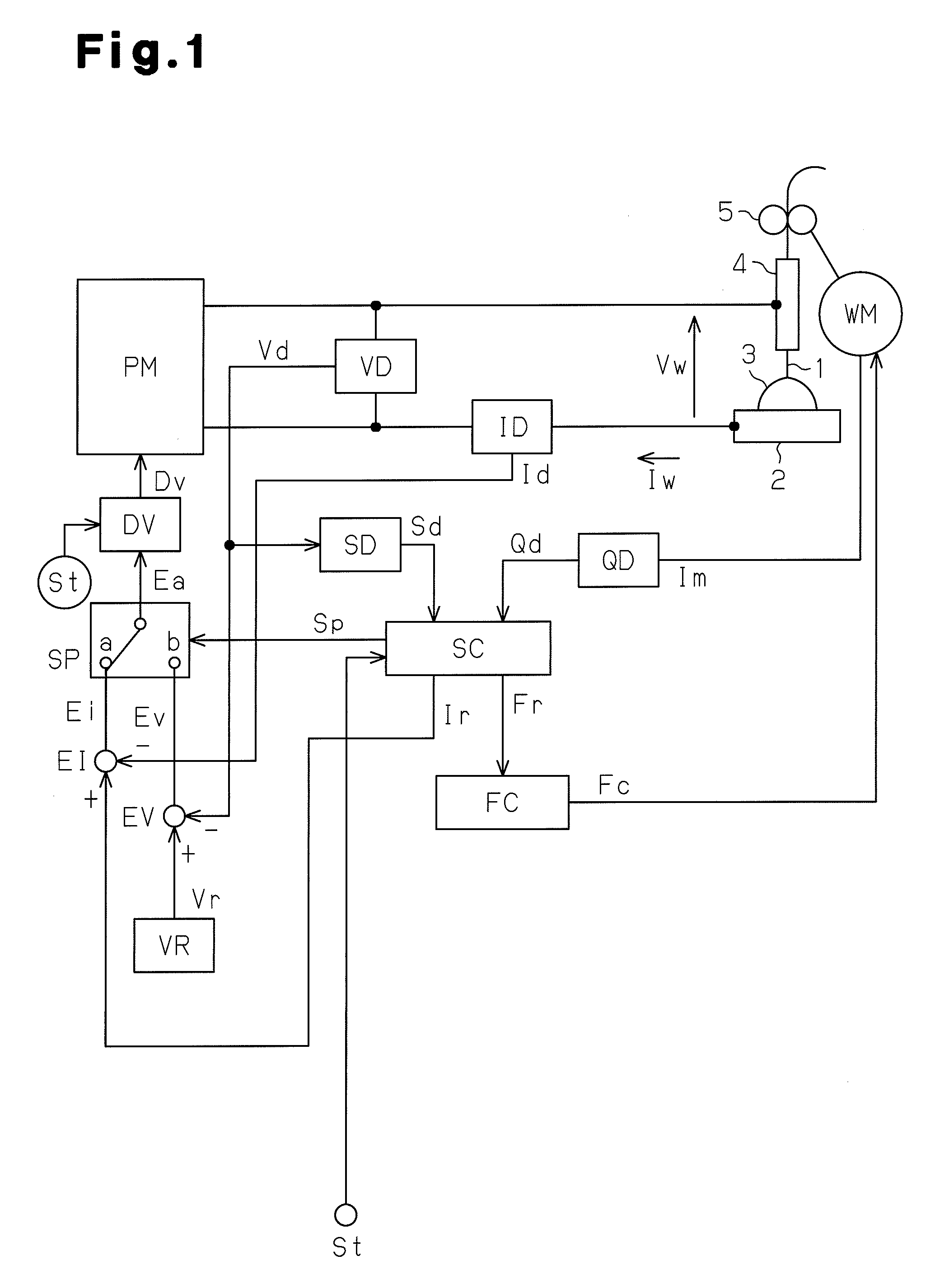
[0032]A first embodiment of the present invention will now be described with reference to the attached drawings. A welding apparatus including a welding power source shown in FIG. 1 is identical with the welding device including the welding power source PS illustrated in FIG. 5.

[0033]As illustrated in FIG. 1, electric power is supplied from a three-phase 200 V commercial power source to a main power source circuit PM. The main power source circuit PM performs output control such as inverter control in accordance with a drive signal Dv, which will be described below. The main power source circuit PM outputs a welding voltage Vw and a welding current Iw to generate an arc 3. The main power source circuit PM is comprised of a primary rectifying circuit, a capacitor, an inverter circuit, a high frequency transformer, a secondary rectifying circuit, and a direct current reactor. The primary rectifying circuit rectifies the commercial power source. The capacitor smoothes the rectified DC ...

second embodiment

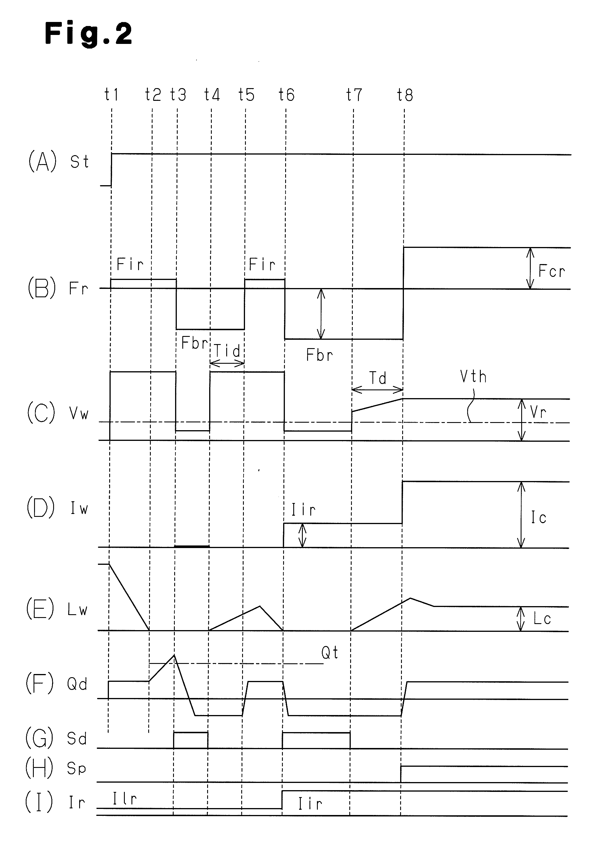
[0057]Next, an arc start control method according to a second embodiment of the present invention will be described with reference to FIG. 3. In the second embodiment, operations executed during the period from time point t1 to time point t3 in FIG. 3 are the same as those in FIG. 2, and the explanation thereof is omitted.

(3) Short Circuit Period from Time Point t3 to Time Point t4

[0058]At time point t3, a part of the insulating material adhered to the distal end of the welding wire is destroyed or removed by a strong pressing force caused by the advance of the welding wire. Then, the welding wire and the base material are electrically connected to each other and short circuited. The short circuit determination signal Sd is changed from the Low level to the High level, as shown in FIG. 3(G). The value of the feed torque signal Qd (short circuit determination torque value) at this time is the reference torque value Qt or greater, as shown in FIG. 3(F). At this time, the current setti...

third embodiment

[0063]An arc start control method according to a third embodiment of the present invention will be described with reference to FIG. 4. In the third embodiment, operations different from those in FIG. 2 will be described.

[0064]During a period from time point t2 to time point t3 while the welding wire is pressed against the base material, a part of insulating material adhered to the distal end of the welding wire is destroyed by the pressing force of the welding wire against the base material, and the resistance value can be transiently greater than the short circuit resistance value. This state continues until the welding wire and the base material are completely short circuited at time point t3. In the transient state, the welding voltage Vw is lower than non-load voltage and higher than the short circuit voltage as shown in FIG. 4(C). In the third embodiment, it is determined that the welding wire is tensed or the welding torch is lifted by determining that the intermediate voltage...


PUM

PropertyMeasurementUnit
Torqueaaaaaaaaaa

Abstract

An arc start control method comprises starting advance of a welding wire, and determining that a distal end of a welding wire contacts a base material and short circuit is caused. If a feed torque value is a reference torque value or greater, the welding wire is retracted and the distal end of the welding wire is separated from the base material without generating an arc. If the feed torque value is smaller than the reference torque value the welding wire is retracted and the distal end of the welding wire is separated from the base material and an initial arc is generated between the welding wire and the base material.

Description

TECHNICAL FIELD[0001]The present invention relates to improvement of a retract arc start control method that generates an initial arc to start consumable electrode arc welding by lifting a welding wire from a base material after causing the welding wire to contact the base material, and switches the initial arc to an arc of a steady state after lifting the welding wire continuously with the initial arc maintained.BACKGROUND ART[0002]As illustrated in FIG. 5, a welding start circuit ST is arranged outside of a welding power source PS. When receiving a welding start signal St from the welding start circuit ST, the welding power source PS outputs a welding voltage Vw and a welding current Iw to generate an arc and a feed control signal Fc to control the feed of a welding wire 1. As the welding start circuit ST, a program logic controller (PLC), which controls welding steps, and a robot controller may be employed. A feed roll 5 is connected to a wire feed motor WM. The welding wire 1 is...

Claims


Application Information

Patent Timeline
IPC IPC(8): B23K9/10
CPCB23K9/0671B23K9/124
Inventor HIROTA, SHUGO
Owner DAIHEN CORP
Why Eureka
Try Eureka