Sticking pad, friction stir welding machine and friction stir welding system

Active Publication Date: 2010-08-26
KAWASAKI HEAVY IND LTD
View PDF15 Cites 23 Cited by
  • Summary
  • Abstract
  • Description
  • Claims
  • Application Information

AI Technical Summary

Benefits of technology

[0035]According to the present invention, the surfaces of the guide rails with which the wheels and the sticking pads come into contact are finished by a predetermined process such that the sticking pads are in contact with the surfaces of the guide arils with a low friction coefficient. Therefore, travel reaction force that acts on the sticking pads when the friction stir welding machine travels can be reduced. Since the friction stir welding machine travels without the wheels coming into contact with the workpieces, it is possible to prevent the workpieces from being damaged by friction stir welding.
[0036]According to the present invention, the guide rails are extended along a weld line corresponding to the joint of the workpieces. The guide rails have the parts extending parallel to the surfaces of the workpieces. The friction stir welding machine travels with the guide members kept in contact with the surfaces of the parts of the guide rails parallel to the surfaces of the workpieces and facing the workpieces. Thus, the reaction force that acts on the welding tool when the welding tool is pressed against the workpieces can be cancelled out even if friction stir welding is carried out at a high welding speed. Thus, the wheels of the friction stir welding machine can be prevented from being separated from the guide rails. Consequently, the friction stir welding machine can achieve intended travel and can weld the workpieces along the intended weld line by friction stir welding

Problems solved by technology

Thus, the gantry type friction stir welding machine 7

Method used


Image

  • Sticking pad, friction stir welding machine and friction stir welding system
  • Sticking pad, friction stir welding machine and friction stir welding system
  • Sticking pad, friction stir welding machine and friction stir welding system

Examples


first embodiment

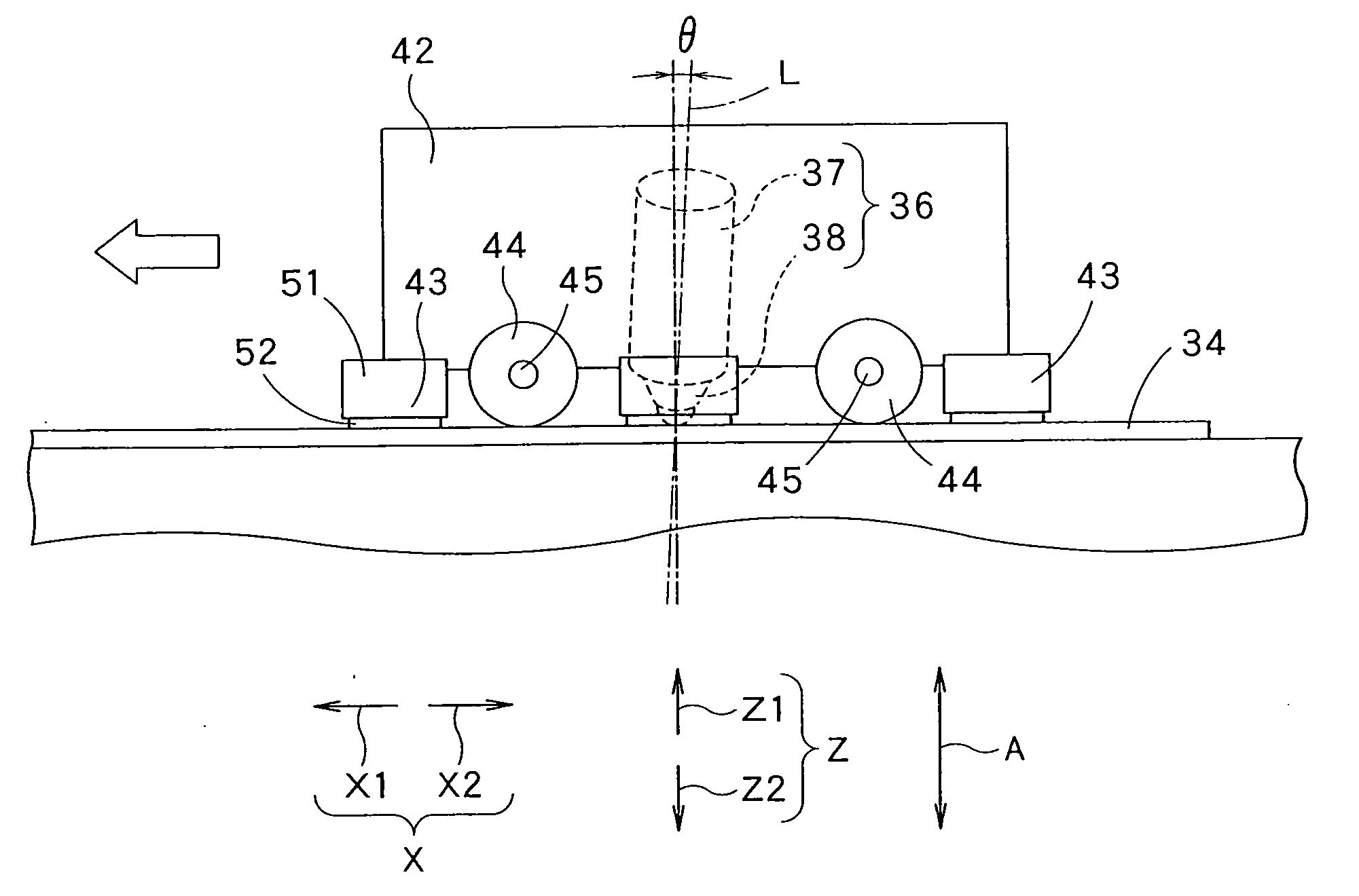
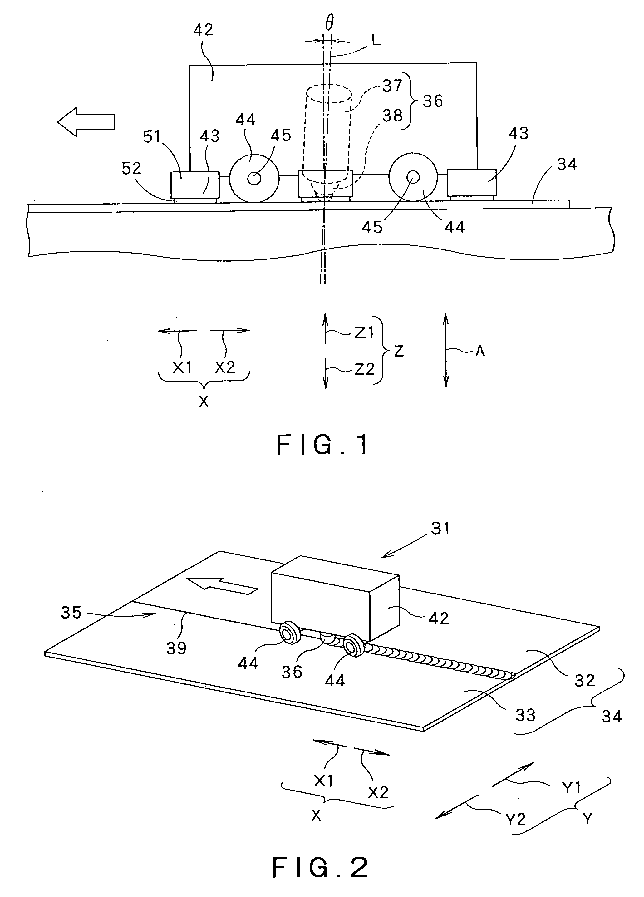
[0062]FIG. 1 is a typical side elevation of a friction stir welding machine 31 (hereinafter, referred to simply as “welding machine 31”) in a first embodiment according to the present invention. FIG. 2 is a perspective view of the welding machine 31 in operation.

[0063]The welding machine 31 welds a workpiece 34 formed by placing two workpieces 32 and 33 edge to edge. A joint 35 is formed between the workpieces 32 and 33 joined edge to edge. A welding tool 36 included in the welding machine 31 is moved continuously along the joint 35 to weld the workpieces 32 and 33 together. A joint line 39, namely, a boundary line between the workpieces 32 and 33, is formed in the surface of the joint 35. In this embodiment, the joint line 39 is straight.

[0064]The welding machine 31 provided with the cylindrical welding tool 36 carries out friction stir welding with the welding tool 36. The welding tool 36 has a substantially cylindrical main part 37, and a tapered pin 38 axially projecting from on...

second embodiment

[0101]The welding machine 59 is provided with wheels 44 and is disposed such that the wheels 44 roll on surfaces 62a (hereinafter, referred to as guide surfaces 62a″) of the webs 62 of the guide rails 61. The wheels 44 roll on the guide surfaces 62a when the welding machine 59 moves. Sticking pads 46 come into contact with and stick to the guide surfaces 62a of the guide rails 61. In the second embodiment, the guide rails 61 are objects to which the sticking pads 46 stick. Each of the sticking pads 46 is attached to the lower end of an L-shaped, arm 85 attached to a frame included in a vehicle 42.

[0102]The guide rails 61 are fixed to, for example, a surface plate 63 on which the workpiece 34 is placed. End parts of the guide rails 61 extend beyond the opposite ends of the workpiece 34 with respect to a traveling direction X. The guide rails 61 are fixed to the surface plate 63 by angles attached to the surface plate 63 with bolts or by welding.

[0103]The guide rails 61 are fixed to, ...

third embodiment

[0113]Axles 45 respectively supporting wheels 44 of the third embodiment extend from the wheels 44 in the lateral direction Y beyond the outer ends of the longitudinal guide strips 75, respectively. Each of the first guide members 72 includes a down support arm 77 extending in the downward vertical direction Z2 from the outer end of the axle 45, a first shaft 78 penetrating a lower part on the side of the downward vertical direction Z2 of the down support arm 77 in the lateral direction Y, fixed to the down support arm 77 and extending in the lateral direction Y toward the guide rail 74, and a cylindrical first roller 79 rotatably supported on the first shaft 78. The first roller 79 and the first shaft 78 are coaxial. The first roller 79 rotates about an axis parallel to the lateral direction Y. The welding machine 71 travels in the traveling direction X for friction stir welding with the first rollers 79 in contact with the down support arms 77.

[0114]A friction stir welding procedu...


PUM

PropertyMeasurementUnit
Stiffnessaaaaaaaaaa
Friction coefficientaaaaaaaaaa

Abstract

A lightweight, mobile friction stir welding machine, a sticking pad for the friction stir welding machine, and a friction stir welding system are provided. The sticking pad has a flat base member facing an object, an annular sealing member protruding from one of major surfaces of the base member so as to surround a central area of the surface of the base member, a slippery member attached to the end surface of the annular sealing member facing the object, and one or some deformation-suppressing protrusions protruding from the surface facing the object of the base member. The slippery member is made of a material that can make the slippery member contact the object with a friction coefficient lower than that with which the sealing member can be in contact with the same object.

Description

TECHNICAL FIELD[0001]The present invention relates to a friction stir welding machine for welding together plural workpieces by friction stirring, a sticking pad employed in the friction stir welding machine, and a friction stir welding system.BACKGROUND ART[0002]A known friction stir welding machine provided with a welding tool is used for carrying out a method of welding plural workpieces together.[0003]FIG. 17 is a typical perspective view of a moving table type friction stir welding machine 1. The friction stir welding machine 1 includes a welding tool 2, a work table for supporting workpieces 3 thereon, and a base 5 on which the work table 4 is moved unidirectionally. The work table 4 supporting the workpieces 3 thereon is moved in a moving direction indicated by the arrow 6. The welding tool 2 can be moved toward and away from the work table 4. The rotating welding tool 2 is pressed against the workpieces 3 and the joint of the workpieces 3 extending along a weld line is welde...

Claims


Application Information

Patent Timeline
IPC IPC(8): B23K20/12
CPCB23K20/1245B23K37/0294F16B47/00B23K2203/10B23K2201/18B23K2101/18B23K2103/10B23K20/12B23K20/26B23K37/02
Inventor FUJIMOTO, MITSUONISHIDA, HIDEHITO
Owner KAWASAKI HEAVY IND LTD
Why Eureka
Try Eureka