Irradiation Field Forming Device

a technology of forming device and irradiation field, which is applied in the direction of heat measurement, instruments, therapy, etc., can solve the problems of difficult treatment planning, difficult method, and difficult three-dimensional filling of the affected area of the specimen with a uniform irradiation spo

Inactive Publication Date: 2010-08-26
NAT INST OF RADIOLOGICAL SCI
View PDF6 Cites 17 Cited by
  • Summary
  • Abstract
  • Description
  • Claims
  • Application Information

AI Technical Summary

Benefits of technology

[0013]According to the present invention, the beam diameter can be maintained constant by the two or more than two converging electromagnets arranged in the downstream of the range shifter, while an irradiation depth of the charged particle beam is regulated by the range shifter.

Problems solved by technology

However, this method is not easy since there are many components to be controlled in the accelerator, and further, an accurate control is required for each of the components.
As a result, a treatment planning has been difficult.
Especially, in the spot scanning method, three-dimensional filling out of the affected area of the specimen with a uniform irradiation spot becomes difficult.

Method used


Image

  • Irradiation Field Forming Device
  • Irradiation Field Forming Device
  • Irradiation Field Forming Device

Examples


first embodiment

[0021]First, a first embodiment will be explained. The first embodiment is a case of irradiating a specimen with a charged particle beam by the spot scanning method.

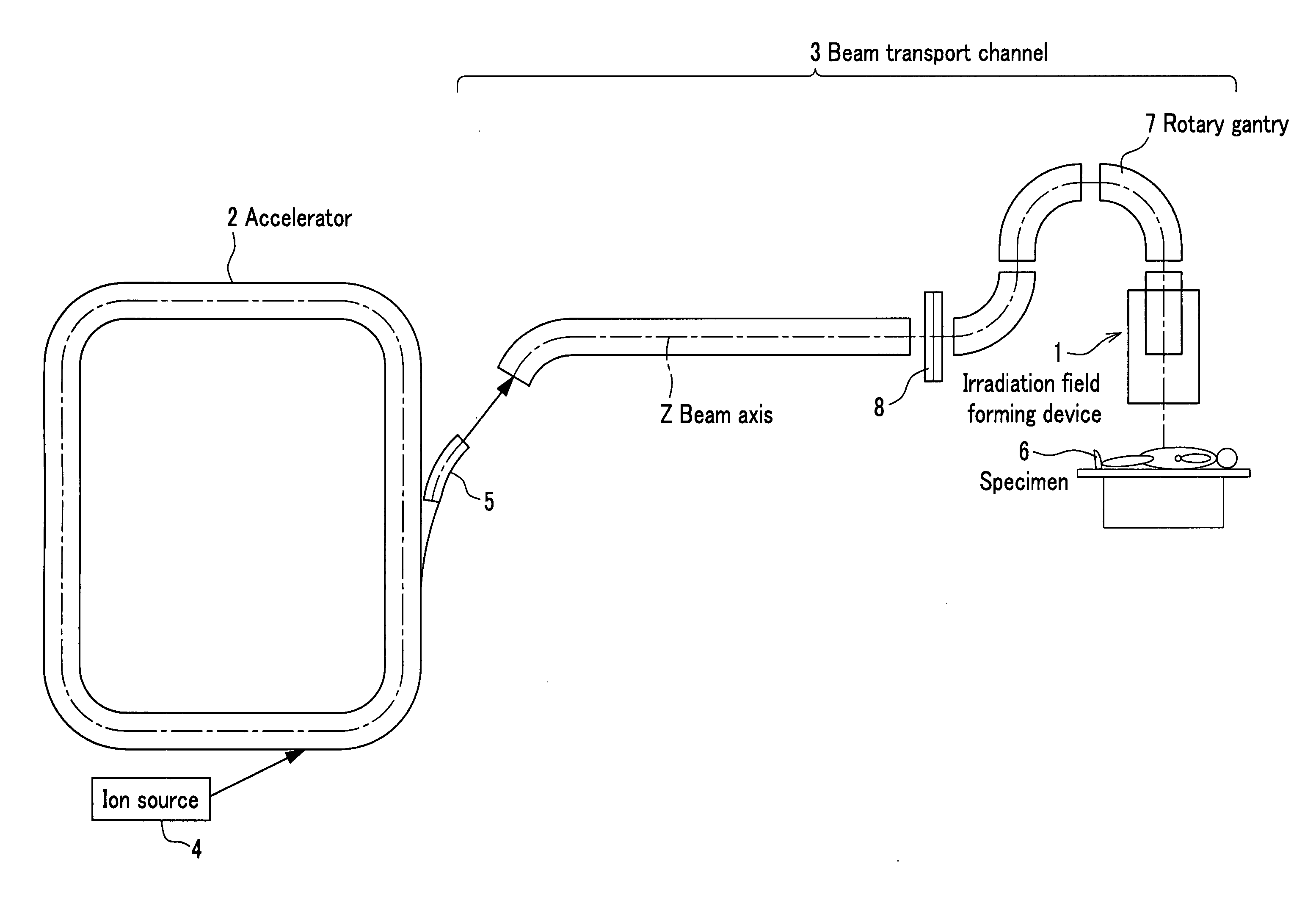
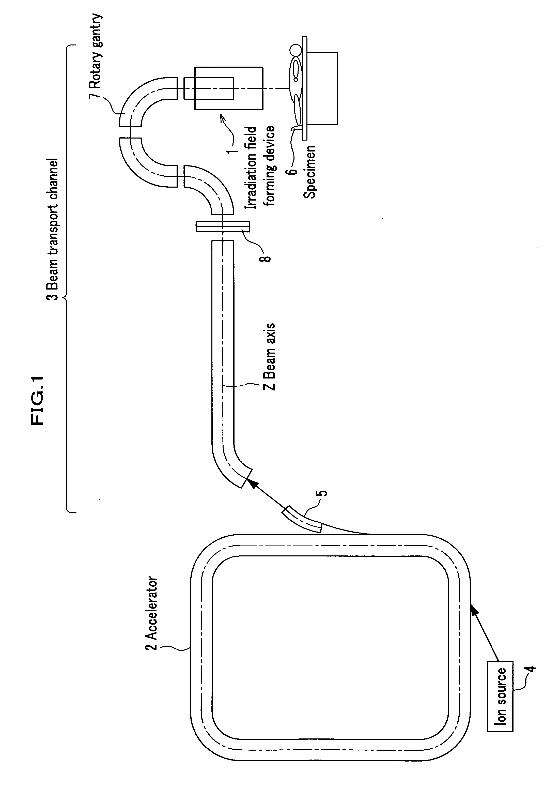
[0022]FIG. 1 is a schematic view for explaining a whole constitution according to the present embodiment. As shown in FIG. 1, an irradiation field forming device 1 is located in the downstream of a beam transport channel 3 which is capable of communication with an accelerator 2. In FIG. 1, charged particles ionized by an ion source 4 are introduced into the accelerator 2. The accelerator 2 accelerates the charged particles by giving energy to the charged particles, while circulating the charged particles, to generate a charged particle beam (hereinafter, referred to as beam). The generated beam is exit from the accelerator 2 via an exit deflector 5 and reaches the irradiation field forming device 1 through the beam transport channel 3. Next, the irradiation field forming device 1 forms an irradiation field with a constan...

second embodiment

[0055]Next, a second embodiment will be explained. The second embodiment is a case that the specimen 6 is irradiated with a charged particle beam by a Wobbler method. It is noted that in explanations of the second embodiment, a duplicated explanation with the first embodiment described above will be omitted.

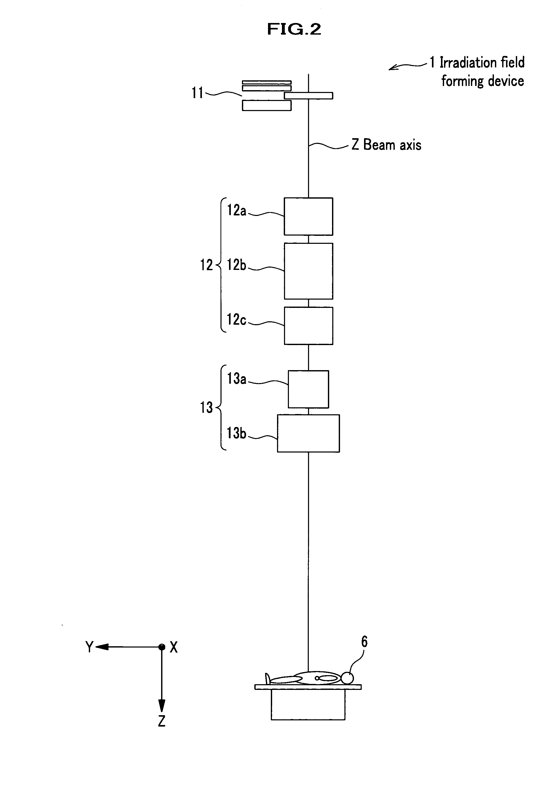
[0056]FIG. 6 is a schematic constitutional view of an irradiation filed forming device 1 according to the second embodiment. As shown in FIG. 6, in the irradiation field forming device 1, the range shifter 11, three quadrupole electromagnets 12 for converging the beam, two deflection electromagnets 13, a scatterer 14, a ridge filter 15, a collimator 16, and a bolus 17 are sequentially disposed on the beam axis Z of the charged particle beam along a beam traveling direction.

[0057]The scatterer 14 is made of, for example, aluminum, tantalum, and lead and scatters the beam to enlarge a diameter of the beam with which the specimen 6 is irradiated.

[0058]The ridge filter 15 expands an ...


PUM


Abstract

An irradiation field forming device for forming an irradiation field when a specimen is irradiated with a charged particle beam generated by an accelerator, the irradiation field forming device includes: a range shifter arranged on a beam axis of the charged particle beam for regulating an irradiation depth of the charged particle beam; and two or more than two converging electromagnets arranged in the downstream of the range shifter for regulating a beam diameter of the charged particle beam which is enlarged by the range shifter to a constant value.

Description

TECHNICAL FIELD[0001]This invention generally relates to an irradiation field forming device for forming an irradiation field of a charged particle beam generated by an accelerator, and more particularly relates to an irradiation field forming device for forming the irradiation field with a constant beam diameter regardless of an irradiation depth.BACKGROUND ART[0002]In recent years, as a new medical treatment for cancers, a charged particle beam treatment which irradiates a charged particle beam on an affected area of a specimen has been expected. Heavy ions represented by, for example, a proton and a carbon ion are included in charged particles to be used for the medical treatment.[0003]Dose of common radiation ray such as X-ray or γ-ray is high in a portion just under a body surface and gradually decreases according to a depth from the body surface. On the contrary, dose of a charged particle beam is low in a portion close to the body surface and rapidly increases to achieve a pe...

Claims


Application Information

Patent Timeline
Patent Type & Authority Applications(United States)
IPC IPC(8): H01J37/141H01J1/50
CPCA61N5/1043A61N2005/1087H05H7/12G21K1/093G21K5/04A61N2005/1095
Inventor FURUKAWA, TAKUJINODA, KOUJI
Owner NAT INST OF RADIOLOGICAL SCI
Why Eureka
Try Eureka