Edram including metal plates

Active Publication Date: 2010-08-26
GLOBALFOUNDRIES US INC
View PDF8 Cites 11 Cited by
  • Summary
  • Abstract
  • Description
  • Claims
  • Application Information

AI Technical Summary

Problems solved by technology

A disadvantage associated with this prior method is that the poly-Si upper electrode has a relatively high electrical resistivity as compared to elemental metals.
The high electrical resistivity of the poly-Si material, as the top electrode, accordingly limits the speed

Method used


Image

  • Edram including metal plates
  • Edram including metal plates
  • Edram including metal plates

Examples


Embodiment Construction

[0023]Detailed embodiments of the present invention are disclosed herein; however, it is to be understood that the disclosed embodiments are merely illustrative of the invention that may be embodied in various forms. In addition, each of the examples given in connection with the various embodiments of the invention is intended to be illustrative, and not restrictive. Further, the figures are not necessarily to scale, some features may be exaggerated to show details of particular components. Therefore, specific structural and functional details disclosed herein are not to be interpreted as limiting, but merely as a representative basis for teaching one skilled in the art to variously employ the present invention.

[0024]The embodiments of the present invention relate to novel methods and structures relating to memory devices. When describing the methods, the following terms have the following meanings, unless otherwise indicated.

[0025]As used herein, the term “memory device” means a st...


PUM


Abstract

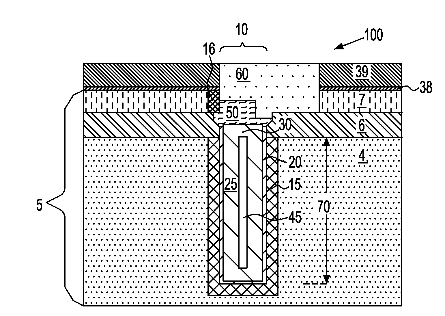
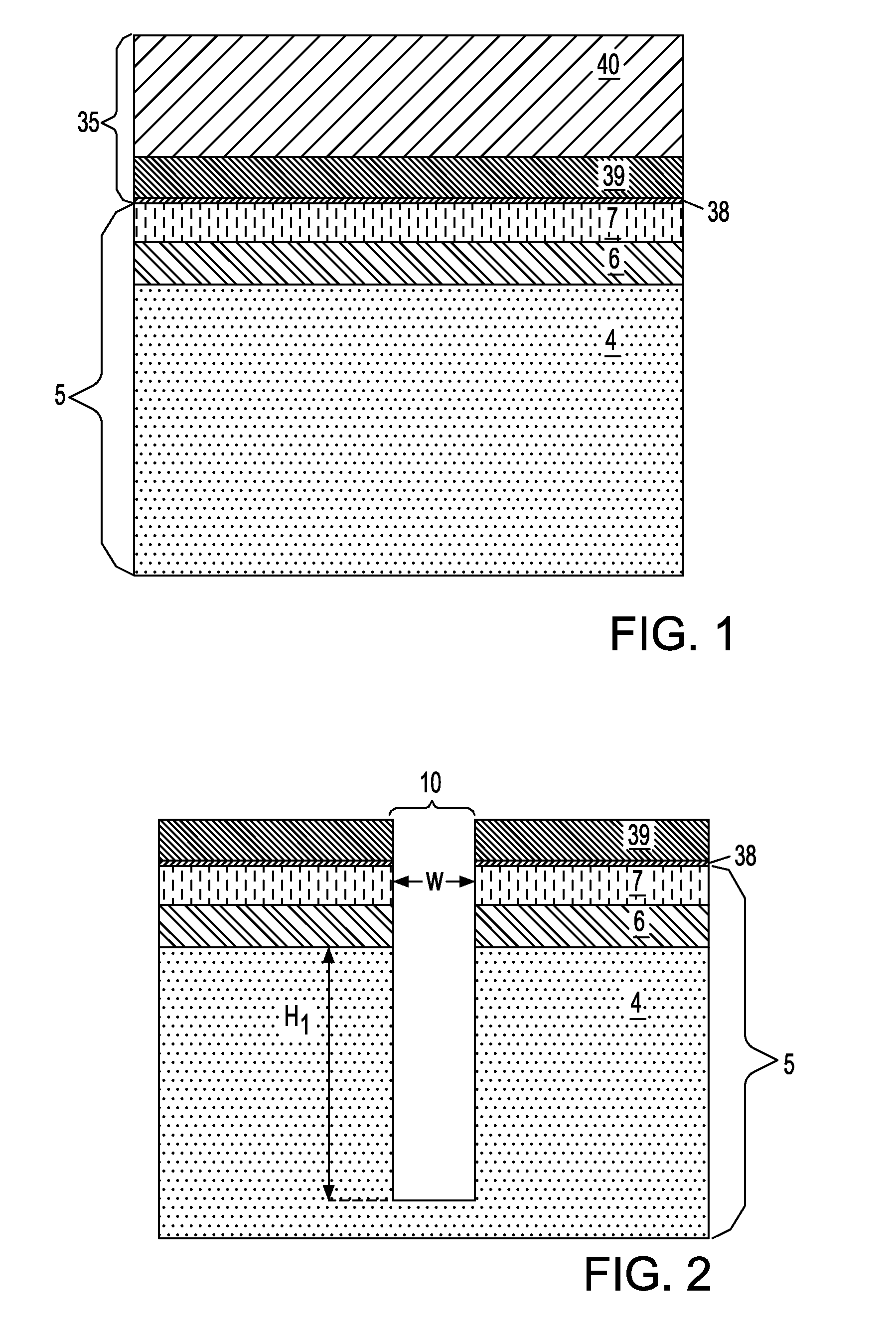
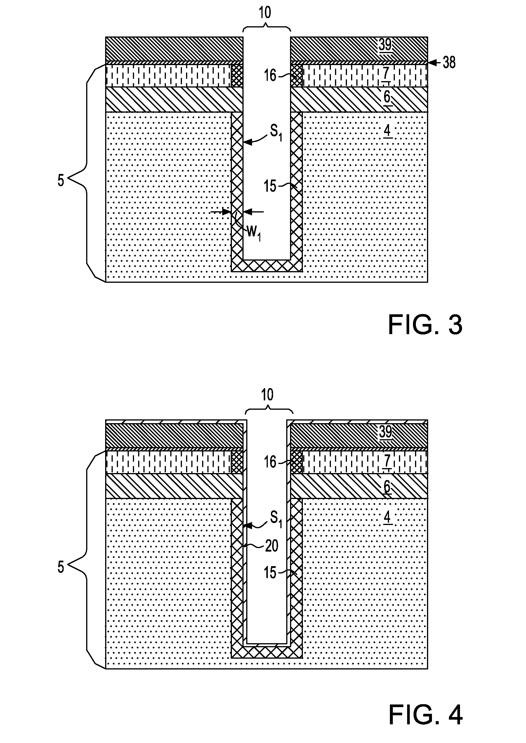
A method for forming a memory device is provided by first forming at least one trench in a semiconductor substrate. Next, a lower electrode is formed in the at least one trench, and thereafter a conformal dielectric layer is formed on the lower electrode.
An upper electrode is then formed on the conformal dielectric layer. The forming of the upper electrode may include a conformal deposition of metal nitride layer, and a non-conformal deposition of an electrically conductive material atop the metal nitride layer, in which the electrically conductive material encloses the at least one trench.

Description

FIELD OF THE INVENTION[0001]The present invention generally relates to a method of fabricating a semiconductor memory device. More particularly, a method and structure are provided in which the lower electrode of the semiconductor memory device is formed by a conformally deposited metal nitride.BACKGROUND OF THE INVENTION[0002]Embedded memory devices fabricated within trench capacitors and / or vertical transistor cells have benefits over planar-stacked device structures. Trench capacitors have replaced the planar storage capacitor in order to meet the scaling demands for high performance DRAM (dynamic random access memory) cell production.[0003]A trench capacitor is a three dimensional device formed by etching a trench into a semiconductor substrate. After trench etching, a buried plate electrode is formed about the exterior portion of the trench and a node dielectric is then formed on the inner walls of the trench. Next, the trench is filled, for example, with N-type polycrystalline...

Claims


Application Information

Patent Timeline
IPC IPC(8): H01L29/92H01L21/02
CPCH01L29/66181H01L28/91
Inventor DYER, THOMAS W.WONG, KEITH KWONG HONKUMAR, MAHENDER
Owner GLOBALFOUNDRIES US INC
Why Eureka
Try Eureka