
Wind turbine generator

a wind turbine generator and wind turbine technology, applied in the direction of electric generator control, machines/engines, mechanical equipment, etc., can solve the problems of reducing the operating rate, excessive current of the power generator, and requiring restarting time, so as to achieve the effect of improving the operating ra

Active Publication Date: 2010-08-26
MITSUBISHI HEAVY IND LTD
View PDF16 Cites 19 Cited by
  • Summary
  • Abstract
  • Description
  • Claims
  • Application Information

AI Technical Summary

Benefits of technology

[0007]The present invention has been made to solve the above-described problem, and an object thereof is to provide a wind turbine generator that can improve the operating rate.
[0010]As described above, the second switch and the first switch have withstand current capabilities that can withstand the occurrence of overcurrent caused by a voltage drop due to a low-voltage event. Therefore, they are not tripped even when a low-voltage event occurs, thus making it possible to maintain the connection state of the power generator and the power system. When current larger than the overcurrent flowing at the low-voltage event flows, the second switch is tripped prior to the first switch, so that tripping of the first switch can be avoided. The second switch can be opened and closed by remote control, it is easily turned on even after tripping thereof.
[0015]According to the present invention, an advantage is afforded in that the operating rate can be improved.

Problems solved by technology

When a voltage drop larger than that in the above-mentioned low-voltage event occurs, there is a possibility of the power generator current becoming excessive, and a circuit breaker that is disposed in the power system and that connects the power generator and the power system becoming tripped before a reduction in the system voltage is detected.
Therefore, there is a problem in that a considerable time is required for restarting, reducing the operating rate.

Method used


Image

  • Wind turbine generator
  • Wind turbine generator
  • Wind turbine generator

Examples


Embodiment Construction

[0028]A wind turbine generator according to one embodiment of the present invention will be described below with reference to the drawings.

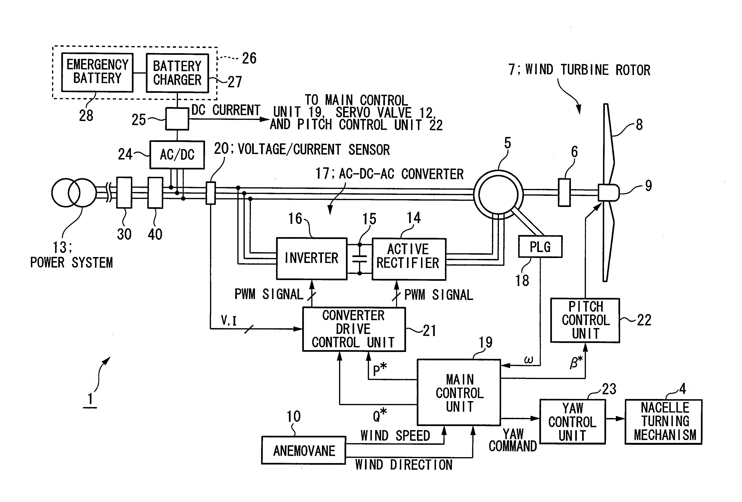
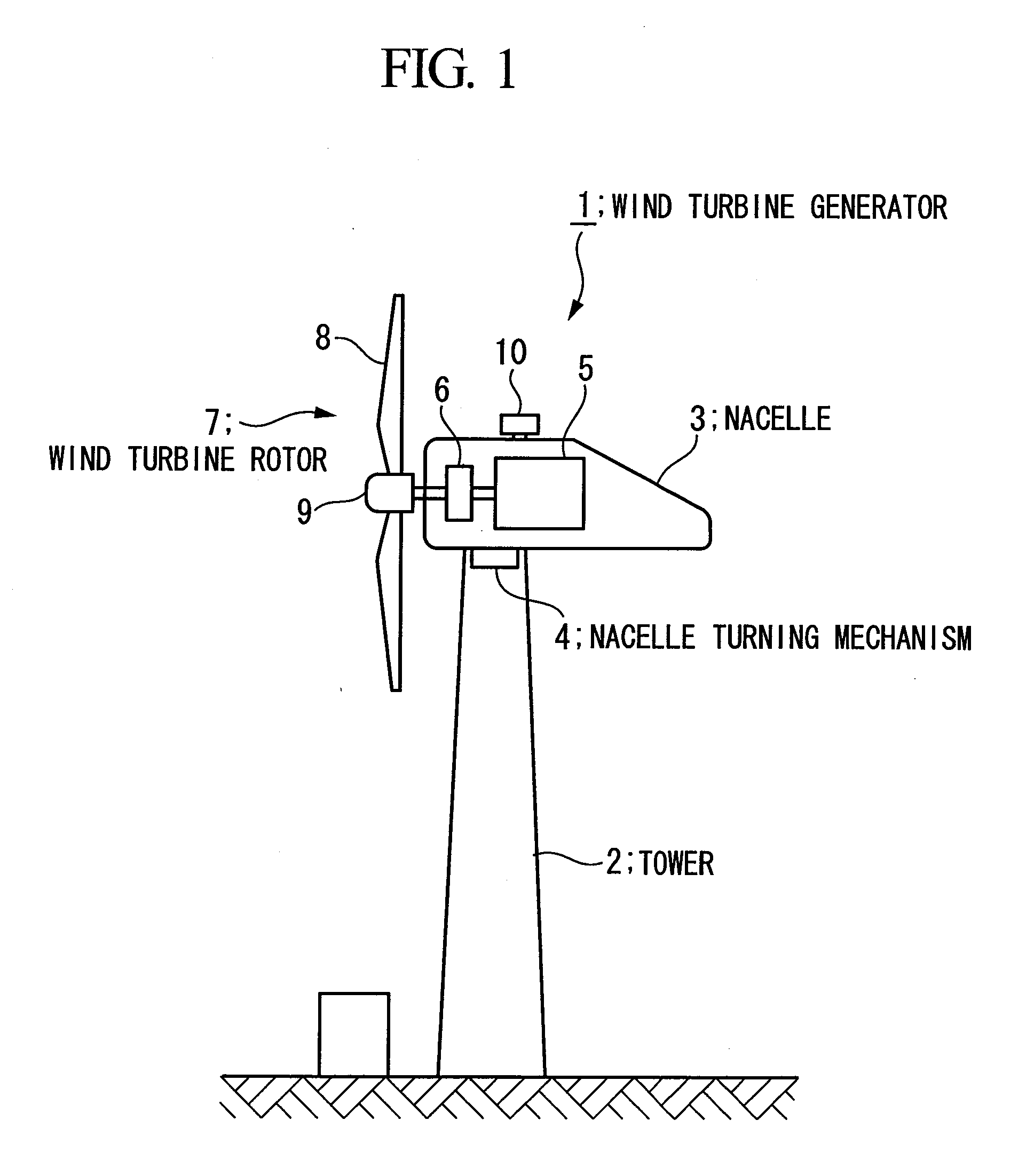
[0029]FIG. 1 is a block diagram showing the overall configuration of the wind turbine generator according to this embodiment. As shown in FIG. 1, the wind turbine generator 1 includes a tower 2 and a nacelle 3 provided at an upper end of the tower 2. The nacelle 3 can turn in a yawing direction and is directed in a desired direction by a nacelle turning mechanism 4. The nacelle 3 includes a power generator 5 and a gear 6. A rotor of the power generator 5 is joined to a wind turbine rotor 7 via the gear 6.

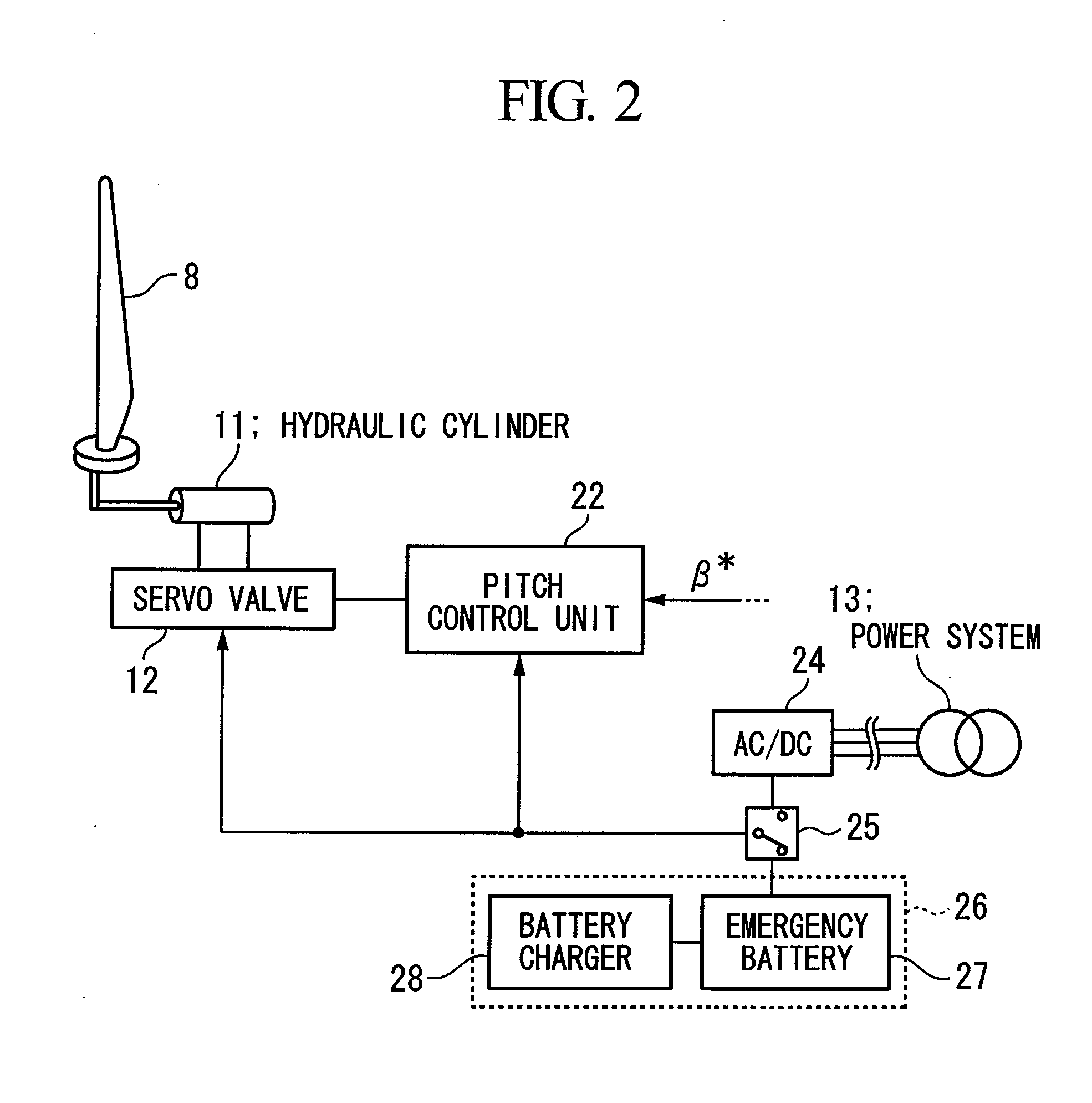
[0030]The wind turbine rotor 7 includes blades 8 and a hub 9 that supports the blades 8. The blades 8 are provided such that their pitch angle is variable. Specifically, as shown in FIG. 2, the hub 9 accommodates a hydraulic cylinder 11 that drives the blades 8 and a servo valve 12 that supplies hydraulic pressure to the hydraulic cylinder 11. Th...


PUM


Abstract

An object is to improve the operating rate. A first switch is provided in a power line connecting a power generator to a power system, and a second switch that can be opened and closed by remote control is provided in the power line between the power generator and the first switch. In the second switch, a withstand current capability is set that allows current flowing in a low-voltage event and that withstands current having a value equal to or less than a current value specified by the thermal setting of the power generator. In the first switch, a withstand current capability is set that is superior to the withstand current capability of the second switch and that withstands current having a value equal to or less than the current value specified by the thermal setting of the power generator.

Description

TECHNICAL FIELD[0001]The present invention relates to wind turbine generator.BACKGROUND ART[0002]In wind-turbine operation control, an operation is employed in which, if the system voltage is reduced due to the occurrence of a power failure or the like, the connection between a wind turbine and a power system is immediately disconnected to avoid damage to a power generator etc. caused by overcurrent. On the other hand, for example, if a low-voltage event such as that shown in a voltage reduction pattern etc. required by LVRT (low voltage ride-through) occurs, the connection between the wind turbine and the power system needs to be maintained to continuously operate the wind turbine.[0003]Patent Citation 1:[0004]U.S. Pat. No. 6,921,985DISCLOSURE OF INVENTION[0005]When a voltage drop larger than that in the above-mentioned low-voltage event occurs, there is a possibility of the power generator current becoming excessive, and a circuit breaker that is disposed in the power system and t...

Claims


Application Information

Patent Timeline
IPC IPC(8): H02P9/04
CPCH02J3/48H02J3/50H02J3/386Y02E10/763Y02E10/725H02J2300/28H02J3/381H02J3/46Y02E10/76Y02E10/72
Inventor ARINAGA, SHINJIMATSUSHITA, TAKATOSHIWAKASA, TSUYOSHISHIBATA, MASAAKIYASUGI, AKIRA
Owner MITSUBISHI HEAVY IND LTD
Learn More