Spark plug for internal combustion engines and method for manufacturing the spark plug

a technology for internal combustion engines and spark plugs, which is applied in the manufacture of spark plugs, spark plugs, manufacturing tools, etc., can solve the problems of increased amount of precious metals used, increased cost of manufacturing spark plugs, and increased demand voltage, so as to achieve the effect of low cos

Active Publication Date: 2010-08-26
DENSO CORP
View PDF8 Cites 22 Cited by
  • Summary
  • Abstract
  • Description
  • Claims
  • Application Information

AI Technical Summary

Benefits of technology

[0014]The present invention has been made in order to solve the issue described above, and has as its object to provide a spark plug for internal-combustion engines that offers excellence in durability and reliability in the joint portion at low cost.

Problems solved by technology

However, there are the following problems in the above-mentioned spark plug 9.
Thereby, the precious-metal-chip 953 is worn and there is a possibility that demand voltage may become large.
Further, in order to lower demand voltage, it is necessary to make a spark discharge gap G formed between the center electrode 94 and the precious-metal-chip 953 small, but in this case, the amount of the precious metals used will increase, and there is a possibility that the cost of manufacturing the spark plug 9 may rise.

Method used


Image

  • Spark plug for internal combustion engines and method for manufacturing the spark plug
  • Spark plug for internal combustion engines and method for manufacturing the spark plug
  • Spark plug for internal combustion engines and method for manufacturing the spark plug

Examples


first embodiment

[0071]The first embodiment is explained with reference to FIGS. 1-11.

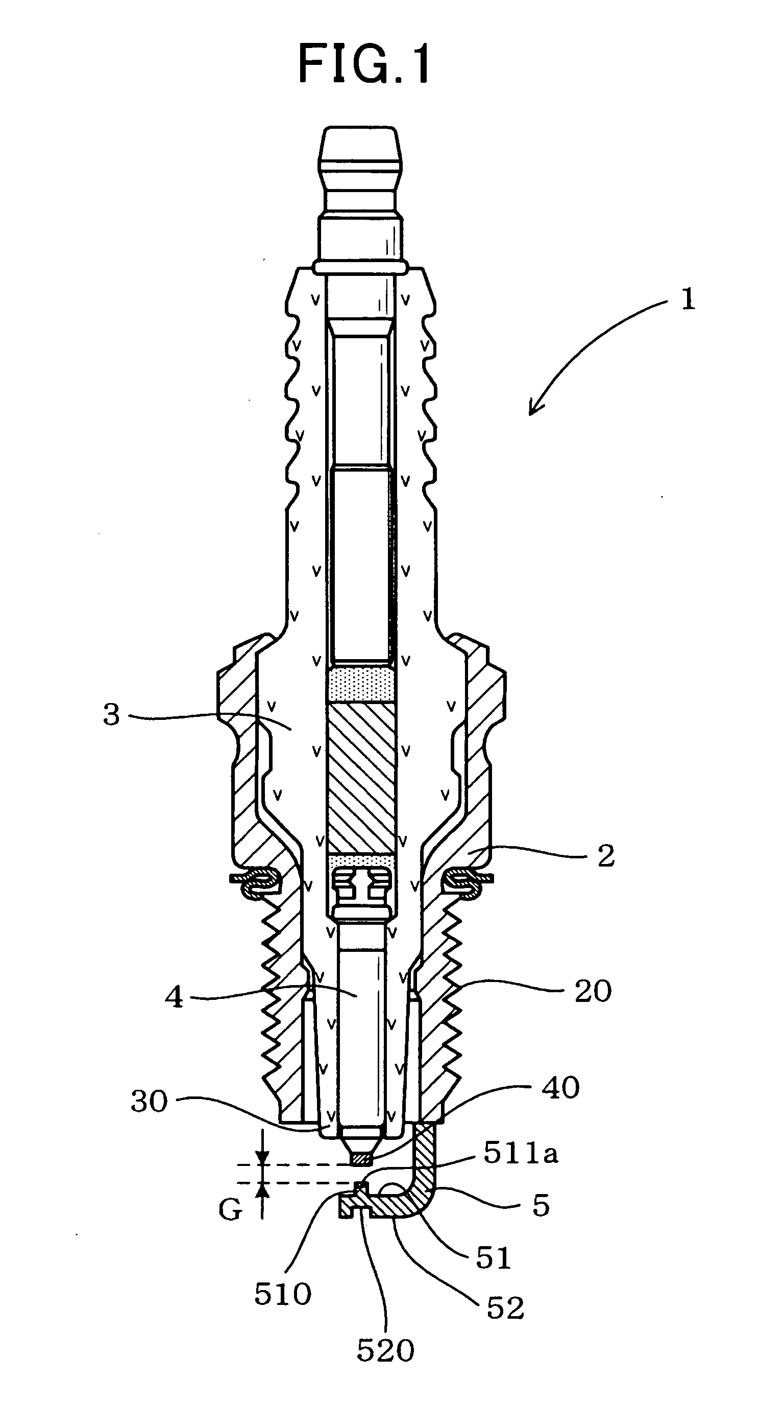
[0072]A spark plug 1 of the present embodiment has a mount fitting 2, a porcelain insulator 3, a center electrode 4, and a ground electrode 5, as shown in FIG. 1.

[0073]Specifically, the mount fitting 2 has a screw part 20 for attachment formed on its own perimeter.

[0074]The porcelain insulator 3 is held inside the mount fitting 2 while it has an insulator tip part 30 arranged so that its tip side is projected outwardly from the mount fitting 2.

[0075]The center electrode 4 is held inside the porcelain insulator 3 while it has an electrode tip part 40 arranged so that its tip side is projected outwardly from the porcelain insulator 3.

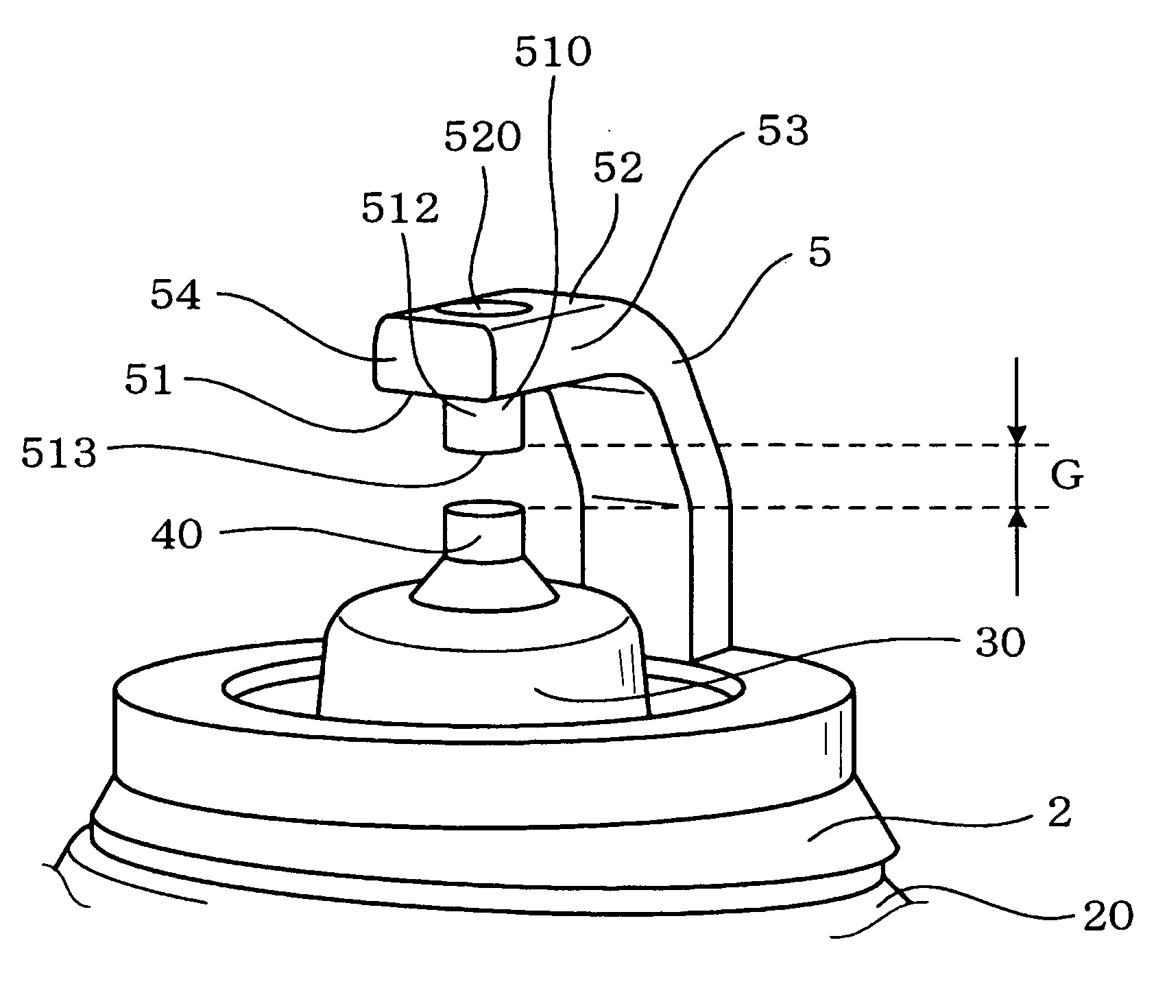
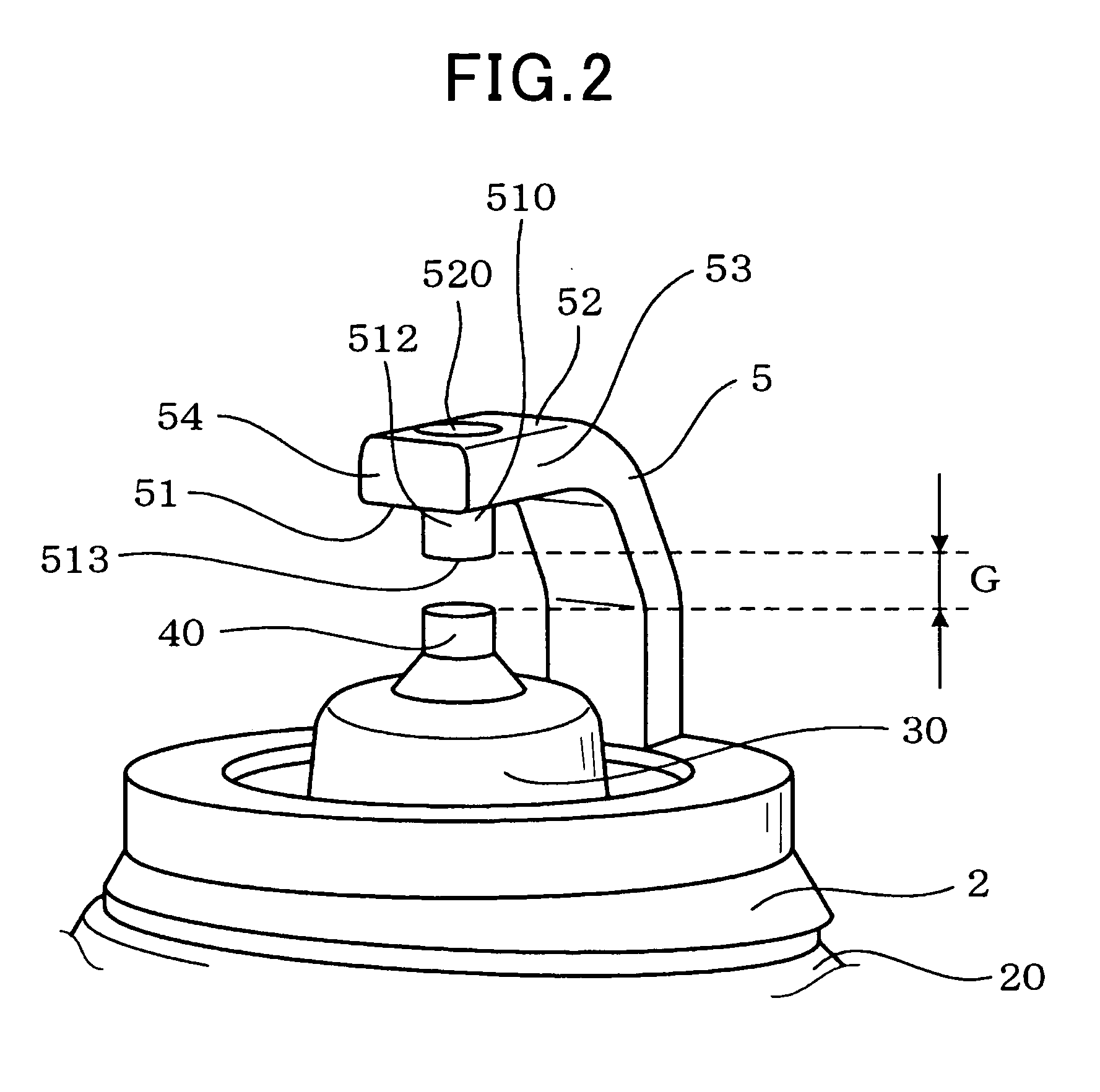
[0076]Moreover, a spark discharge gap G is formed between the ground electrode 5 and the center electrode 4.

[0077]The ground electrode 5 is fixed to the mount fitting 2, while the ground electrode 5 has a convex portion 510. The convex portion 510 is made of a part of base materials of t...

second embodiment

The Second Embodiment

[0162]The second embodiment is explained with reference to FIGS. 12-16. It should be appreciated that in this second embodiment and the embodiment hereafter, the same reference numbers are used for the same constituent factors as the spark plug given in the first embodiment mentioned above, and that explanation is omitted or simplified.

[0163]The second embodiment, as shown in FIGS. 12-16, is an example regarding the spark plug 1 that has a different form from the above-mentioned first embodiment, and method of manufacturing it.

[0164]The ground electrode 5 of the spark plug 1 in the present embodiment has a taper part 516 formed so that width becomes narrower as its tip portion nears a tip side, as shown in FIG. 16.

[0165]Moreover, the convex portion 510 having the same shape with the taper part 516 is formed in the opposing surface 51 side of the taper part 516. The taper angle (refer to A in FIG. 16) of the taper part 516 may be designed into 12.5-45 degrees.

[01...

third embodiment

The Third Embodiment

[0174]The third embodiment is explained with reference to FIG. 17.

[0175]The third embodiment, as shown in FIG. 17, is an example of the ground electrode 5 that has the convex portion 510 and the concave portion 520 with near square pole shapes.

[0176]That is, the ground electrode 5 of the present embodiment is manufactured by using the metal die 6 that has cavity 61 for convex portion and the pressing jig 7, both in near square pole shape.

[0177]In the spark plug 1 of the present embodiment, when a cross-section area of a section of the convex portion 510 that intersects perpendicularly in an axial direction of the spark plug 1 is set to a and a cross-section area of a section of the concave portion 520 that intersects perpendicularly in an axial direction of the spark plug 1 is set to A, the relation of A>=a is satisfied.

[0178]Here, when seeing the convex portion 510 and concave portion 520 from the axial direction of the spark plug 1, both have squares-like shape...


PUM

PropertyMeasurementUnit
widthaaaaaaaaaa
widthaaaaaaaaaa
diameteraaaaaaaaaa

Abstract

A spark plug for internal-combustion engines equipped with a center electrode and a ground electrode is provided. In the spark plug, the ground electrode is fixed to a mount fitting, while the ground electrode has a convex portion. The convex portion is made of a part of base materials of the ground electrode where the part is facing the center electrode, and is projected toward the center electrode. The convex portion has a fusion solidification part made of precious metal materials and a part of the base materials melted together and solidified at least on part of an electric discharge surface facing the center electrode.

Description

CROSS-REFERENCE TO RELATED APPLICATION[0001]This application is based on and claims the benefit of priority from earlier Japanese Patent Application No. 2009-009643 filed on Jan. 20, 2009, the description of which is incorporated herein by reference.BACKGROUND OF THE INVENTION[0002]1. Technical Field of the Invention[0003]This invention relates to a spark plug for internal combustion engines used for automobiles, cogenerations, gas feeding pumps, etc. and a method for manufacturing the spark plug.[0004]2. Description of the Related Art[0005]Spark plugs are still used abundantly as an ignition means of a fuel-air mixture introduced into a combustion chamber of internal-combustion engines used for automobiles, etc.[0006]As an example, a spark plug disclosed in Japanese Patent Application Laid-Open Publication No. 11-204233 is known.[0007]The spark plug disclosed in the publication is shown in FIGS. 34 and 35. As shown in the figures, the spark plug 9 has a center electrode 94 and a gr...

Claims


Application Information

Patent Timeline
Patent Type & Authority Applications(United States)
IPC IPC(8): H01T13/32H01T21/02
CPCB23K9/0026H01T21/02H01T13/32
Inventor KAWASHIMA, YASUSHIHANASHI, KEN
Owner DENSO CORP
Why Eureka
Try Eureka