Multi-band antenna and wireless communication device including the same

a wireless communication device and antenna technology, applied in the direction of separate antenna unit combinations, resonant antennas, radiating elements structural forms, etc., can solve the problems of obstructing the miniaturization of the terminal, increasing the manpower cost of the antenna, and increasing the space occupied by the antenna, so as to achieve easy installation and fine tuning of the antenna

Inactive Publication Date: 2010-08-26
E M W ANTENNA CO LTD
View PDF8 Cites 19 Cited by
  • Summary
  • Abstract
  • Description
  • Claims
  • Application Information

AI Technical Summary

Benefits of technology

[0019]According to the present invention, the multi-band antenna has two or more frequency bands so as to provide different two or more services.
[0020]Further, according to the present invention, the multi-band antenna can independently adjust two more frequency bands to enable an easy fine tuning of the antenna and can be easily installed at diverse terminals.

Problems solved by technology

However, in this case, the manufacturing cost of the antenna is increased and a space occupied by the antenna is also increased, thereby obstructing a miniaturization of the terminal.
But, as described above, it is very difficult to implement a multi-band antenna having one or more frequency bands with the center frequencies which are quite different from each other.
A multi-band antenna can be relatively easily implemented using a single radiation element for services having the center frequencies which are in a multiplication relation such as the GSM900 and DSC1800 services, but in case of services having the center frequencies which are not in a multiplication relation such as the GSM900 and DVB-H services or the DCS1800 and DVB-H services and are spaced apart from each other, it is difficult to implement an antenna capable of covering all of them.
Thus, a fine tuning of the antenna becomes difficult, and it is very difficult to properly install the antenna at diverse terminals whose electromagnetic installation environments are different.

Method used


Image

  • Multi-band antenna and wireless communication device including the same
  • Multi-band antenna and wireless communication device including the same
  • Multi-band antenna and wireless communication device including the same

Examples


Embodiment Construction

[0026]A preferred embodiment of the present invention will now be described in detail to with reference to the attached drawings. This is merely an exemplary embodiment, and the present invention is not limited thereto.

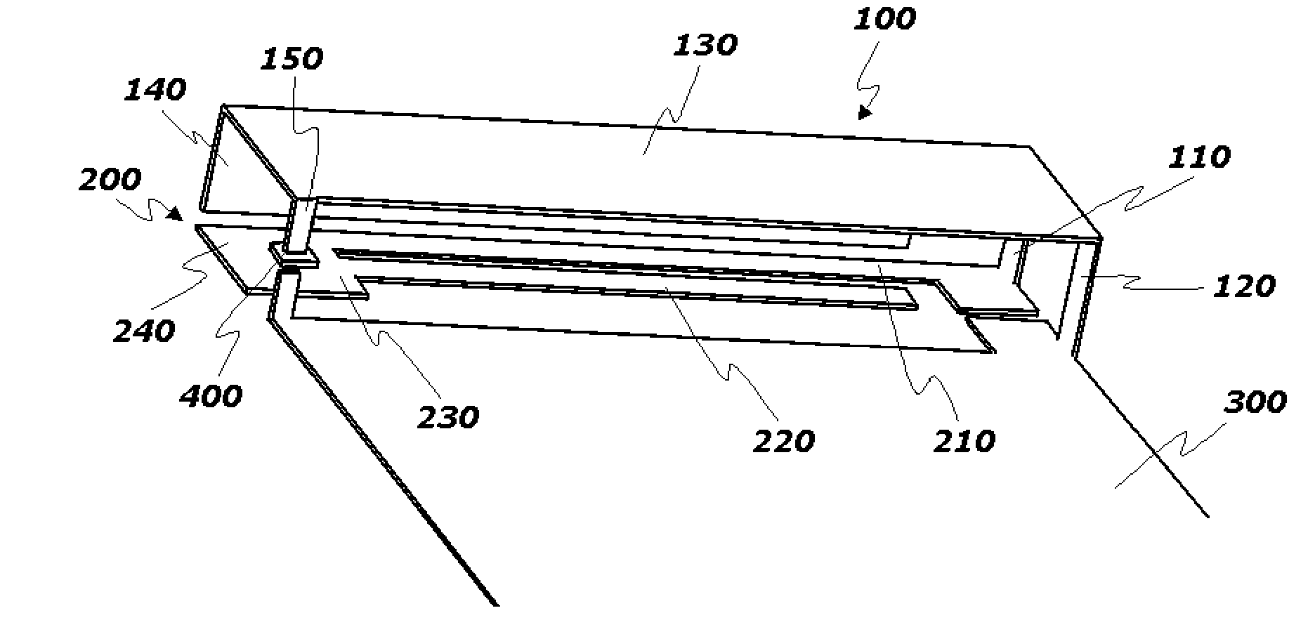
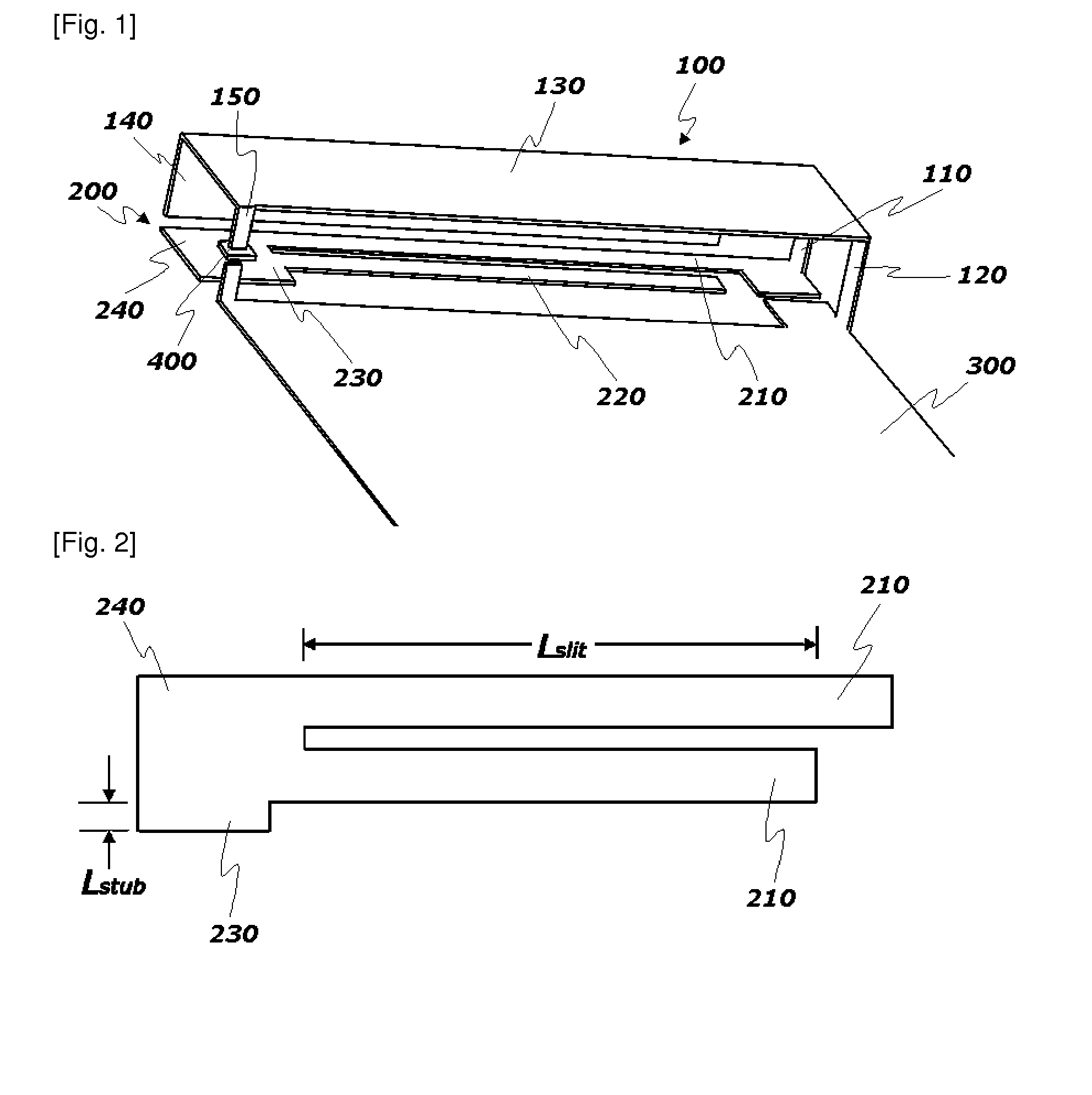
[0027]FIG. 1 is a perspective view showing a multi-band antenna in accordance with an embodiment of the present invention.

[0028]In this embodiment, the multi-band antenna includes a first radiation element 100 for covering a first frequency band and a second radiation element 200 for covering a second frequency band, which are all disposed at one side of a ground plane 300 so as to be fed with power.

[0029]In the meantime, the antenna may further include a dielectric element (not shown) for supporting the first and second radiation elements 100 and 200 and facilitating the installation of the antenna. In this case, the first radiation element 100 and the second radiation element 200 can be displaced on different surfaces of the dielectric element, preferably on the top...


PUM


Abstract

There is herein disclosed a multi-band antenna which can adjust respective frequency bands independently. The multi-band antenna comprises a first radiation element having a PIFA structure and a second radiation element having a monopole structure. Also, a second ground terminal is disposed at one end of the first radiation element so as to be connected to a ground plane through a capacitor. The adjustment of the capacitance enables an independent adjustment of a first frequency band. The second radiation element includes a stub so as to allow the second frequency band to be independently adjusted, and a first sub-element and a second sub-element which defines a slit therebetween so as to allow the third frequency band to be independently adjusted. According to the present invention, it is possible to provide a multi-band antenna which can easily adjust respective frequency bands using multi-bands.

Description

TECHNICAL FIELD[0001]The present invention relates to a multi-band antenna, and more particularly, to a multi-band antenna which can adjust respective frequency bands independently.BACKGROUND ART[0002]In wireless communication in which information is transmitted and received by electromagnetic waves, an antenna in which current is directly induced by the electromagnetic waves or the electromagnetic waves are induced by the current should be indispensably included in a wireless communication device as the most distal element of an analog circuit. It is known that the antenna is classified into a dipole antenna, a monopole antenna, etc., in terms of its structure. A portable wireless communication device prefers the monopole antenna which is small-sized. The monopole antenna is designed to have a length corresponding to one fourths of a resonant wavelength, i.e., a wavelength for the center frequency of a target frequency band, due to the mirror effect of a ground surface, such that t...

Claims


Application Information

Patent Timeline
Patent Type & Authority Applications(United States)
IPC IPC(8): H01Q5/00H01Q9/04H01Q1/24
CPCH01Q1/38H01Q5/00H01Q9/0421H01Q5/40H01Q21/30H01Q5/364H01Q13/10H01Q1/243
Inventor RYOU, BYUNG HOONSUNG, WON MOKIM, JEONG PYO
Owner E M W ANTENNA CO LTD
Why Eureka
Try Eureka