Optical Fiber Cable for Transmission of High Power Laser Energy Over Great Distances

Active Publication Date: 2010-08-26
FORO ENERGY
View PDF133 Cites 99 Cited by
  • Summary
  • Abstract
  • Description
  • Claims
  • Application Information

AI Technical Summary

Benefits of technology

[0015]A spool of optical fiber cable for transmitting laser energy over great distances. The spool having a cable wound around the spool, the cable being capable of being unwound from and wound onto the spool, and thus being rewindable. The cable having a length greater than about 0.5 km, about 1 km, about 2 km or about 3 km and comprising: a core; a cladding; a coating; a first protective layer; an

Problems solved by technology

This deleterious result will effectively clamp the signal output power, but continue to transfer power to the Stokes (reflected) signal via the electrostrictive process which underlies the stimulated Brillouin phenomenon.” Thus, the Corning paper, at page 4, provides that “[s]timuated Brillouin scattering is known to grossly limit the design of several optical transmission systems, amplifiers, and lasers.”
This perceived paradigm, expressed in the art to be believed to exist between length of fiber and power transmittance is further illustrated in the May 31, 2007, Vol. 5, Supplement, pages S39-S41, CHINESE OPTICS LETTERS, Muto et al., ti

Method used


Image

  • Optical Fiber Cable for Transmission of High Power Laser Energy Over Great Distances
  • Optical Fiber Cable for Transmission of High Power Laser Energy Over Great Distances
  • Optical Fiber Cable for Transmission of High Power Laser Energy Over Great Distances

Examples


example 2

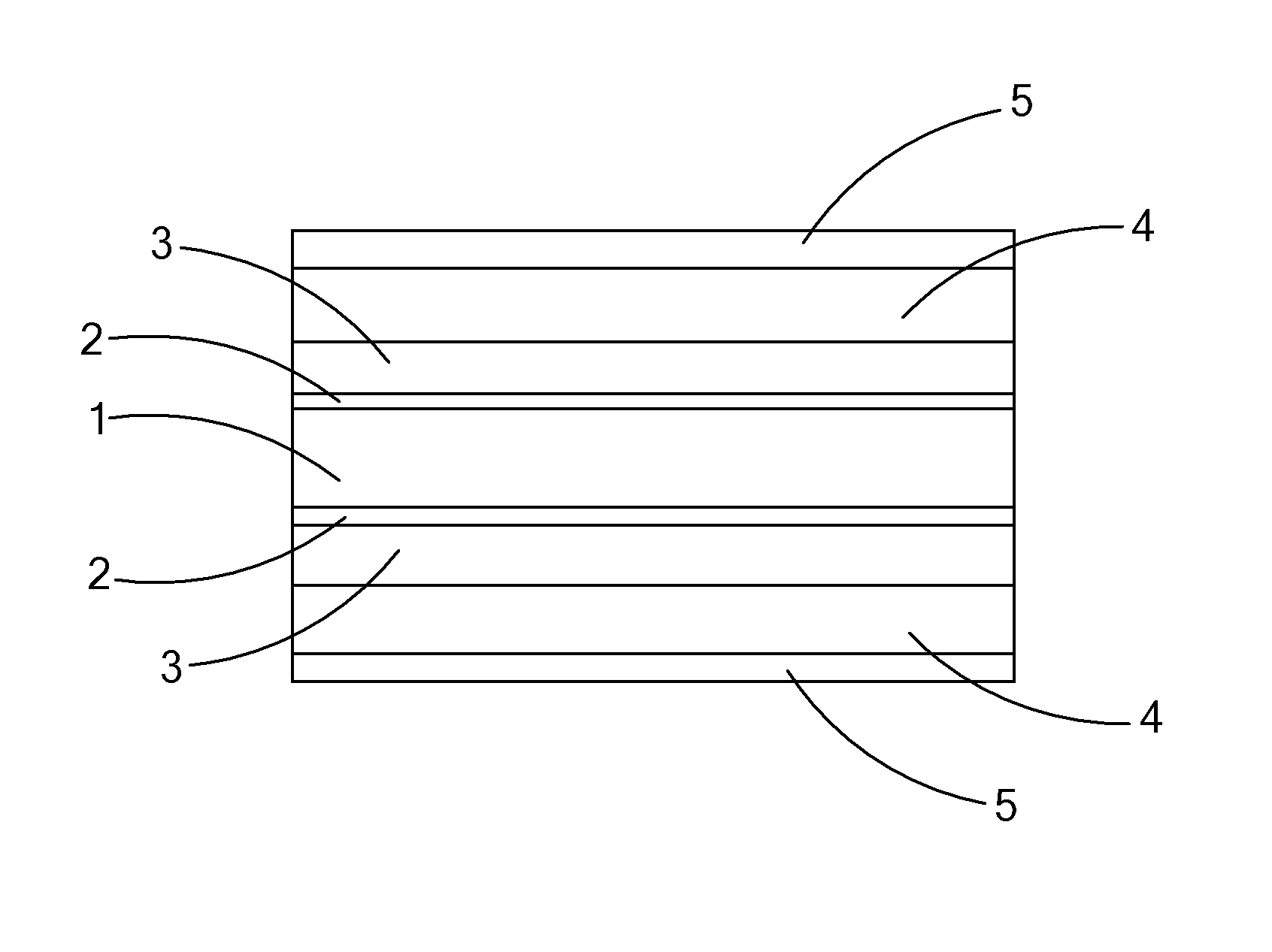
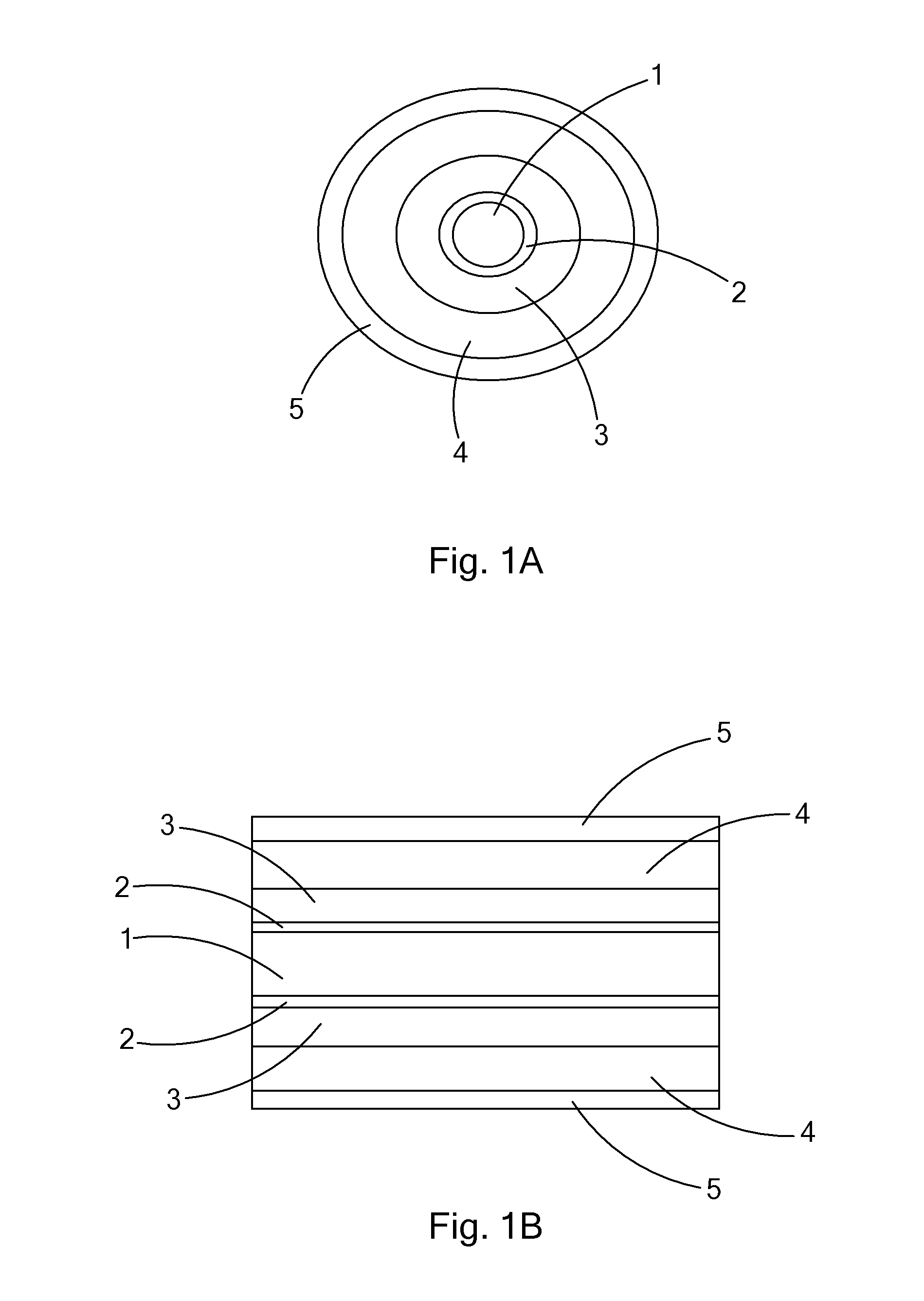
[0035]An example of an embodiment of the optical fiber cable of the present invention would have a fused silica core of about 500 microns diameter, a fluorine doped fused silica cladding, having a thickness of 50 microns, an Acrylate coating having a thickness of about 60 microns, and an ⅛ inch outer diameter stainless steel protective layer and a length of about 2 km. The fiber has a numerical aperture (NA) of 0.22. The fiber of this example transmitted a laser beam (wavelength 1080 nm) of about 10 kW (kilowatt) power, from the preferred laser, over a distance of about 2 km in temperatures of up to about 150 degrees C. and at ambient pressure and with less than 0.8 dB / km power loss.

example 3

[0036]An example of an embodiment of the optical fiber cable of the present invention is a fused silica core of about 600 microns diameter, a fluorine doped fused silica cladding, having a thickness of 60 microns, a high temperature Acrylate coating having a thickness of about 90 microns, and a ⅛ inch outer diameter stainless steel protective layer and a length of about 0.5 km. The fiber had a numerical aperture of 0.17. The fiber of this example transmitted a laser beam (wavelength 1080 nm) of about 10 kW power from the preferred laser, over a distance of about 0.5 km in temperatures of up to about 200 degrees C. and at ambient pressure and with less than 1 dB / km power loss.

example 4

[0037]The preferred IPG 20000 YB laser was operated a duty cycle of 10% for a 1 kHz pulse rate. The operating conditions for this example were established to keep the pulse duration longer than the time constant for SBS. Thus, the absence of SBS was the result of the fiber and laser, not the pulse duration. The laser beam was transmitted through the 2 km fiber of Example 2, evaluated in a test system along the lines of the test system shown in FIG. 3 and provided the results set forth in Table I, where peak power launched and power output are in watts.

TABLE IPeak PowerPeak PowerPercentageLaunchedOutputtransmitted92445248.9153586456.3156384454.0166086452.0181897053.31932104554.12000110055.02224115351.82297121652.92495125050.12632132950.52756142151.63028159252.63421181653.13684198753.93947210553.34342226352.14605238251.74868248751.1

[0038]The spectrum for 4868 Watt power is shown at FIG. 4. The absence of SRS phenomenon is clearly shown in the spectrum. (As used herein terms such as, “...


PUM


Abstract

There is provided a system and apparatus for the transmission of high power laser energy over great distances without substantial power loss and without the presence of stimulated Raman scattering. There is further provided systems and optical fiber cable configurations and optical fiber structures for the delivering high power laser energy over great distances to a tool or surface to perform an operation or work with the tool or upon the surface.

Description

[0001]This application is a continuation-in-part of U.S. patent application Ser. No. 12 / 544,136 filed Aug. 19, 2009, title Method and Apparatus for Delivering High Power Laser Energy over Long Distances, which claims the benefit of the filing date of Oct. 17, 2008 under 35 U.S.C. §119(e)(1) of U.S. Provisional Application Ser. No. 61 / 106,472, titled Transmission of High Optical Power Levels via Optical Fibers for Applications such as Rock Drilling and Power Transmission; and this application claims the benefit of priority under 35 U.S.C. §119(e)(1) of the following listed applications: U.S. Provisional Application Ser. No. 61 / 295,562, filed Jan. 15, 2010, title Optical Fiber Cable for Transmission of High Power Laser Energy Over Great Distances and U.S. Provisional Application Ser. No. 61 / 153,271, filed Feb. 17, 2009, title Method and Apparatus for an Armored High Power Optical Fiber for Providing Boreholes in the Earth; the entire disclosure of each of the above mentioned regular a...

Claims


Application Information

Patent Timeline
IPC IPC(8): G02B6/44
CPCE21B7/14E21B10/60G02B6/4296G02B6/4492G02B6/443G02B6/4436G02B6/4415G02B6/44382E21B7/15E21B17/00G02B6/02395
Inventor ZEDIKER, MARK S.RINZLER, CHARLES C.FAIRCLOTH, BRIAN O.MOXLEY, JOEL F.
Owner FORO ENERGY
Why Eureka
Try Eureka