Method and apparatus for controlling relative coal flow in pipes from a pulverizer

a technology of relative coal flow and pulverizer, which is applied in the direction of lighting and heating apparatus, liquid/fluent solid measurement, instruments, etc., can solve the problems of incomplete combustion/wasting of fuel, excessive emissions, and high maintenance costs, so as to reduce pollution, control costs, and control the efficiency of combustion

Inactive Publication Date: 2010-09-02
RHODES GEORGE W
View PDF26 Cites 15 Cited by
  • Summary
  • Abstract
  • Description
  • Claims
  • Application Information

AI Technical Summary

Benefits of technology

[0013]This invention relates to a method by which relative coal flow mass in individual pipes is measured. All coal-fired electric plants utilize pulverizers to grind large pieces of coal into fine particle sizes. Each pulverizer has several pipes through which coal is delivered (4 to 7 is typical) and each pulverizer provides a stream of hot air to a furnace where combustion occurs. The air / coal (A / C) mixture is critical to control costs, control efficiency of combustion, and reduce pollution such as particulate or NOx. If relative coal flow distributed between the pipes is not nearly equal, and A / C is not maintained undesirable results are produced which require costly maintenance. The undesirable results include, but are not limited to, burning division walls and burner tips, incomplete combustion / wasting of fuel and producing excess emissions. Measuring of the relative coal flow of particles at any given time in all pipes provides for control of the coal flow and combustion process.
[0014]In this invention, relative coal flow (not actual measured rates of coal flow) is sensed between the plurality of pipes emanating from a pulverizer and connected to a plurality of burners in a combustion chamber. Applicant has discovered that the known characteristic of the presence of “roping” of coal flow in a coal flow pipe can be used to improve determination of relative coal flow. In the past, attempts to measure coal flow have involved insertion of probes into a pipe, or other attempts to measure coal flow quantitatively. These methods try to avoid measurements in the region of coal flow because the “roping” otherwise interferes with this approach to measurement. In contrast, Applicant seeks to take advantage of the roping phenomenon. In one embodiment, this invention detects the energy of the coal flow in a region of “roping” by detecting acoustic emission from a piezoelectric transducer which is placed in the region of a pipe where roping coal flow impinges upon a pipe surface, such as at a bend. This invention utilizes AE sensors on different pipes and does not compare AE sensors located on a single pipe. AE sensors are attached at similar locations on each coal feeding pipe from a single pulverizer.

Problems solved by technology

If relative coal flow distributed between the pipes is not nearly equal, and A / C is not maintained undesirable results are produced which require costly maintenance.
The undesirable results include, but are not limited to, burning division walls and burner tips, incomplete combustion / wasting of fuel and producing excess emissions.
These methods try to avoid measurements in the region of coal flow because the “roping” otherwise interferes with this approach to measurement.
However, because the rope is not stable in position or amount of material passing a given aperture at a given time, prior art attempted solutions to give reliable relative coal flow determination were not successful.
However, the measurements are always relative and never absolute.

Method used


Image

  • Method and apparatus for controlling relative  coal flow in pipes from a pulverizer
  • Method and apparatus for controlling relative  coal flow in pipes from a pulverizer
  • Method and apparatus for controlling relative  coal flow in pipes from a pulverizer

Examples


example 1

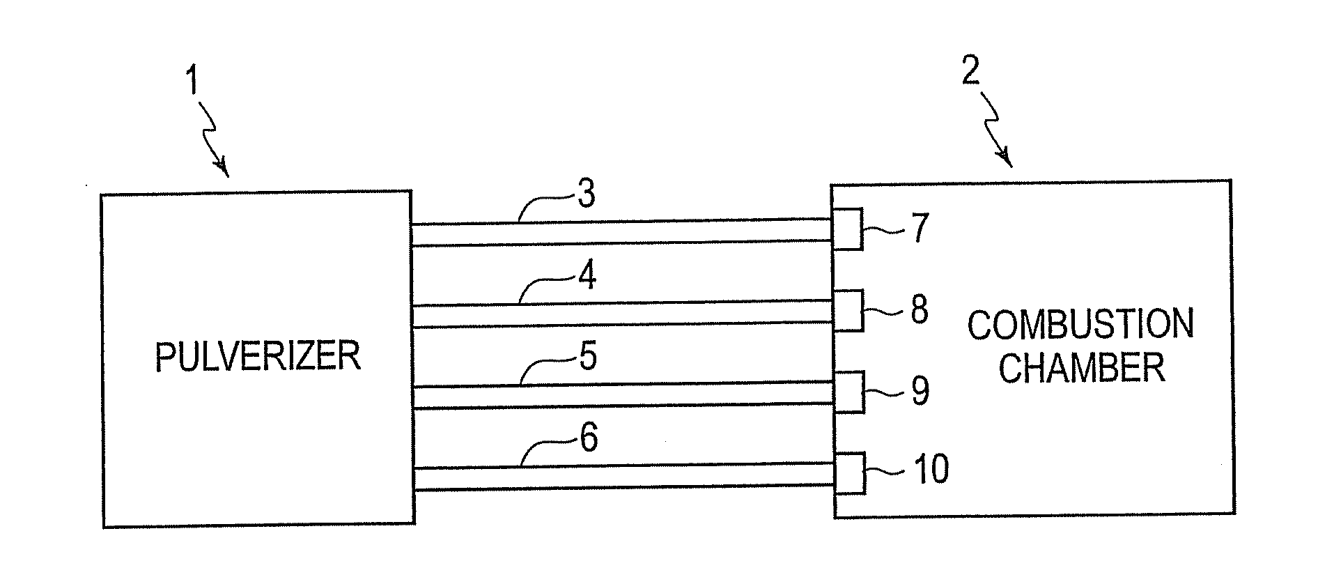
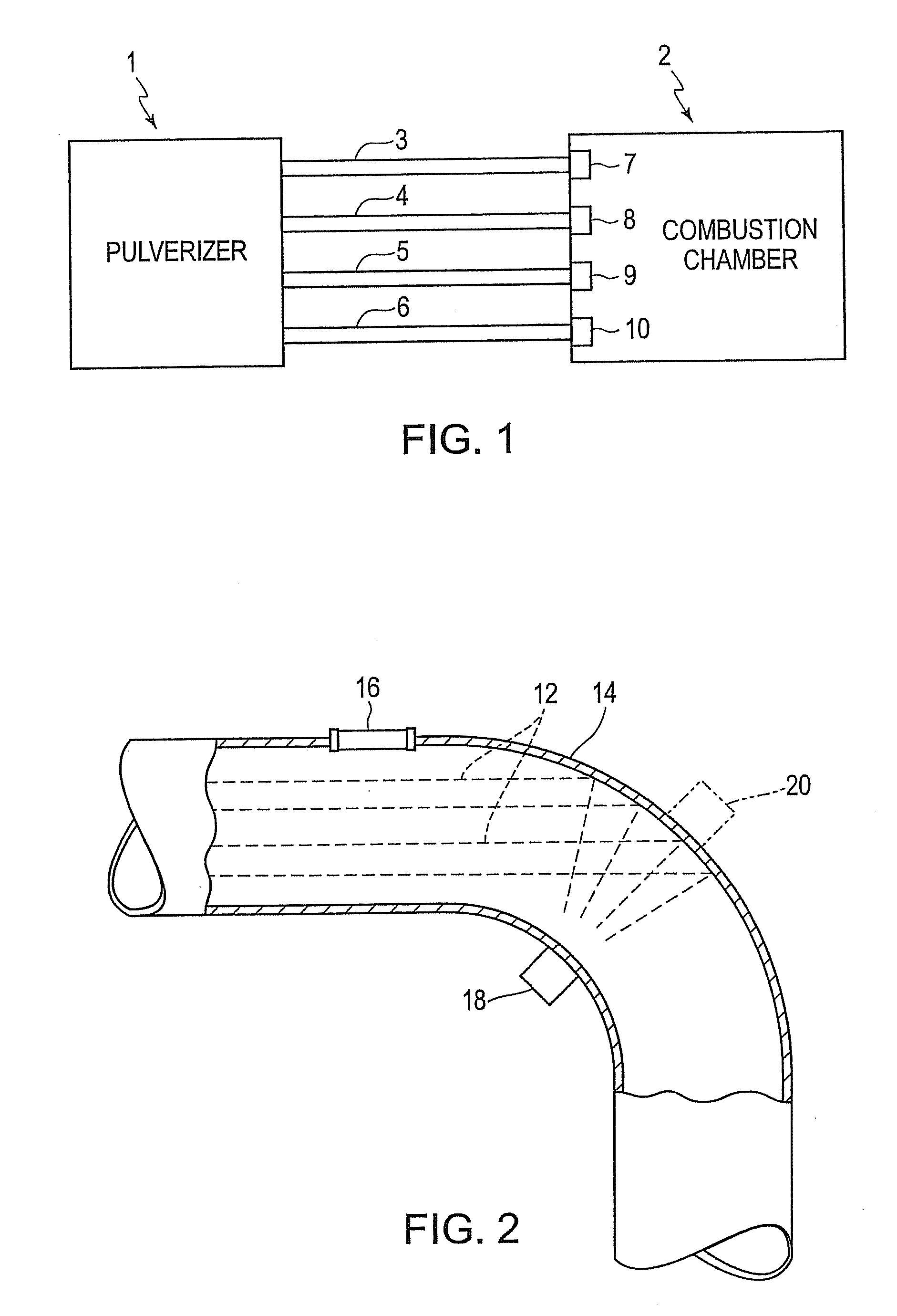
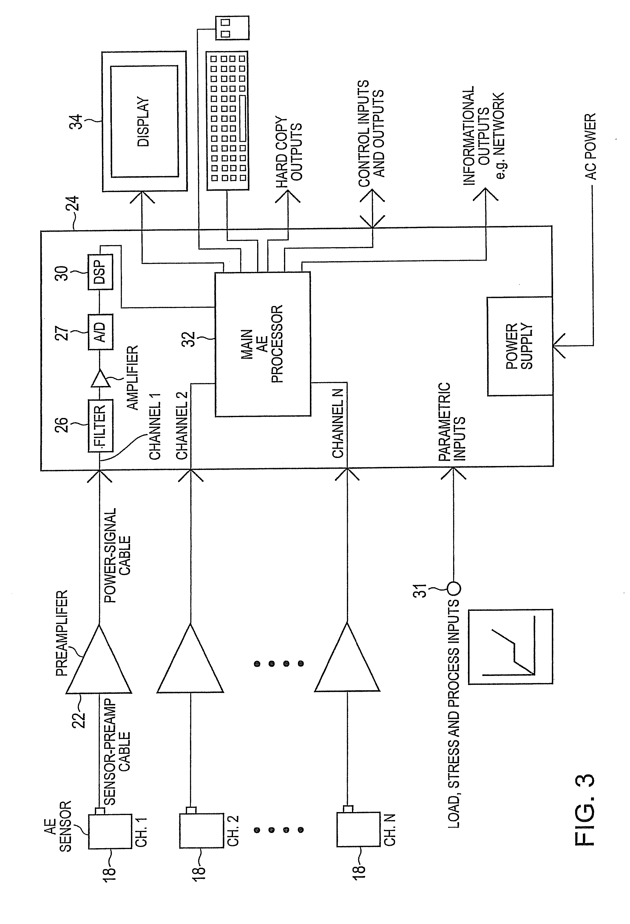
[0075]In the San Juan power plant, unit number 1, owned by Public Service Company of New Mexico (PNM), AE sensors were installed on all coal pipes. In all, there are 16 pipes from four pulverizer mills. The 16 pipes were remotely monitored for AE signals from 150 kHz to 300 kHz. The outputs of the four pulverizers as represented by the 16 pipes are shown in FIGS. 5A-5D. In these figures, the units are in dB and therefore the magnitude between 20 and 60 represents a factor of 10,000. FIG. 5A shows the measurements taken on single sensors located on each of the four coal pipes connecting mill A to unit 1. Similarly, FIG. 5B shows outputs of sensors connected to the four pipes from mill B, FIG. 5C shows the outputs of four sensors connected to pipes of mill C, and FIG. 5D shows the outputs of sensors connected to four pipes of mill D. All of the outputs shown in FIGS. 5A-5D represent the 16 pipes providing coal air mixtures to the San Juan unit 1.

[0076]In FIGS. 5A-5D, different channel...

example 2

[0082]In FIG. 6A-6D, there is shown data which was taken to determine if the data were indeed valid data which could be relied upon. In the data, it is seen that there are apparent imbalances, and it was unknown whether the imbalances were real or the sensors were not mounted at positions which would yield correct relative data. To determine this, redundant sensors were attached to each location and it was found that the data seen was indeed correct.

example 3

[0083]In FIGS. 7A-7D, measurements were taken when mill C (FIG. 7C) was shut down while at the same time mill B (FIG. 7B) was started up. These measurements show the comparative data in the four sets of pipes associated with each of the mills taken with single sensors attached to each of the 16 pipes associated with mills A-D.


PUM

PropertyMeasurementUnit
resonant frequencyaaaaaaaaaa
velocityaaaaaaaaaa
velocityaaaaaaaaaa

Abstract

Pulverizer coal flow pipes feed a mixture of air and coal to burners in electric utility coal fire facilities. A method and apparatus for sensing relative coal flow in the pipes uses acoustic emission (AE) sensors to detect flow in each pipe. Sensed relative flow in the pipes is used to balance flow in the pipes and to further adjust pipe coal flow. Sensed flow is used with control parameters of a furnace to maximize power plant efficiency and to ensure compliance with emissions requirements.

Description

[0001]This application claims the benefit of U.S. Provisional Application No. 60 / 929,322, filed Jun. 21, 2007.BACKGROUND[0002]1. Field of the Invention[0003]This invention relates to control of coal flow from a plurality of pipes which are fed by a pulverizer to coal-fired burners such as are used in electric utilities. Control of relative coal flow in pipes emanating from a pulverizer is required in order to provide optimum combustion and compliance with emissions standards. Maintenance of balanced coal flow in pipes to burners of a furnace as used in the electric utility industry is desired.[0004]2. Brief Description of the Related Art[0005]The use of a pulverized air / coal mixture for firing power plants is known. Pulverizers grind coal having relative large particle sizes into smaller particle sizes and mix the particles with air. The output of a pulverizer is a high velocity, high volume of hot air containing coal particles. An air / coal ratio is maintained constant. Pulverizers ...

Claims


Application Information

Patent Timeline
Patent Type & Authority Applications(United States)
IPC IPC(8): G01N29/14F23N5/26G01N29/30G01F1/20
CPCG01F1/74G01F1/666
Inventor RHODES, GEORGE W.CARLOS, MARK F.DONAHUE, JEFF
Owner RHODES GEORGE W
Why Eureka
Try Eureka