Imaging and safety system and method for an industrial machine

a safety system and industrial machine technology, applied in the direction of television system, shape safety device, instruments, etc., can solve the problems of limited application of the system to the bending of sheet materials, aforesaid arrangement has limited application, and the accuracy of the determined angle of bending decreases, so as to improve the speed control of the tool

Active Publication Date: 2010-09-02
LAZER SAFE PTY LTD
View PDF9 Cites 17 Cited by
  • Summary
  • Abstract
  • Description
  • Claims
  • Application Information

AI Technical Summary

Benefits of technology

[0054]A further aspect of the present invention provides a safety system for halting operation of an industrial machine when at least one light beam is interrupted, the system including progressive muting of an effective protection zone.
[0055]Progressive or systematic muting advantageously allows adaptation of the protection zone and / or to allow for enhanced speed control of the of the tool.
[0056]Benefits of the system include, but are not limited to, recognition of interruptions in broad beam (block-rectangular, circular etc) section beams running parallel to and ahead of the tool tip. It will be appreciated that some of the beam may extend behind the tool tip to provide additional protection from incursion entering from above the tool tip, monitoring stopping distance, monitoring press brake tool high and low speeds, and may be used to assist controlling press brake operating speeds, and can monitor mute point position.

Problems solved by technology

Furthermore, characteristics of the press itself, especially tolerance in the construction of the machine and tooling and wear on the tools, and also defamations appearing in the press at the instance of bending can also play a part in the bending angle.
However, such a system is limited in application to the bending of sheet material, and the accuracy of the determined angle of bend decreases with increasing bend angle due to the apparent travel of the light spot decreasing as the material is bent.
However, aforesaid arrangement has limited application in needing to be attached to the lower table of a press and requires relatively complex moving parts and having an prism mounted for rotation about the axis of the image analyser.
Furthermore, the accuracy of flexibility of measurement of the bend angle of the material is limited by the number of holes, and the separation distance between adjacent holes in a radial direction of the encoder from the axis of rotation, such that error in the determination of the bend angle can be significant.
However, with the detectors lying level with and adjacent to the upper surface of the die, such detectors are prone to damage or being accidentally obscured during bending operations and impeding and slowing down the loading and unloading of work pieces eg sheets of metal.
This may lead to lost efficiency or productivity.

Method used


Image

  • Imaging and safety system and method for an industrial machine
  • Imaging and safety system and method for an industrial machine
  • Imaging and safety system and method for an industrial machine

Examples


Embodiment Construction

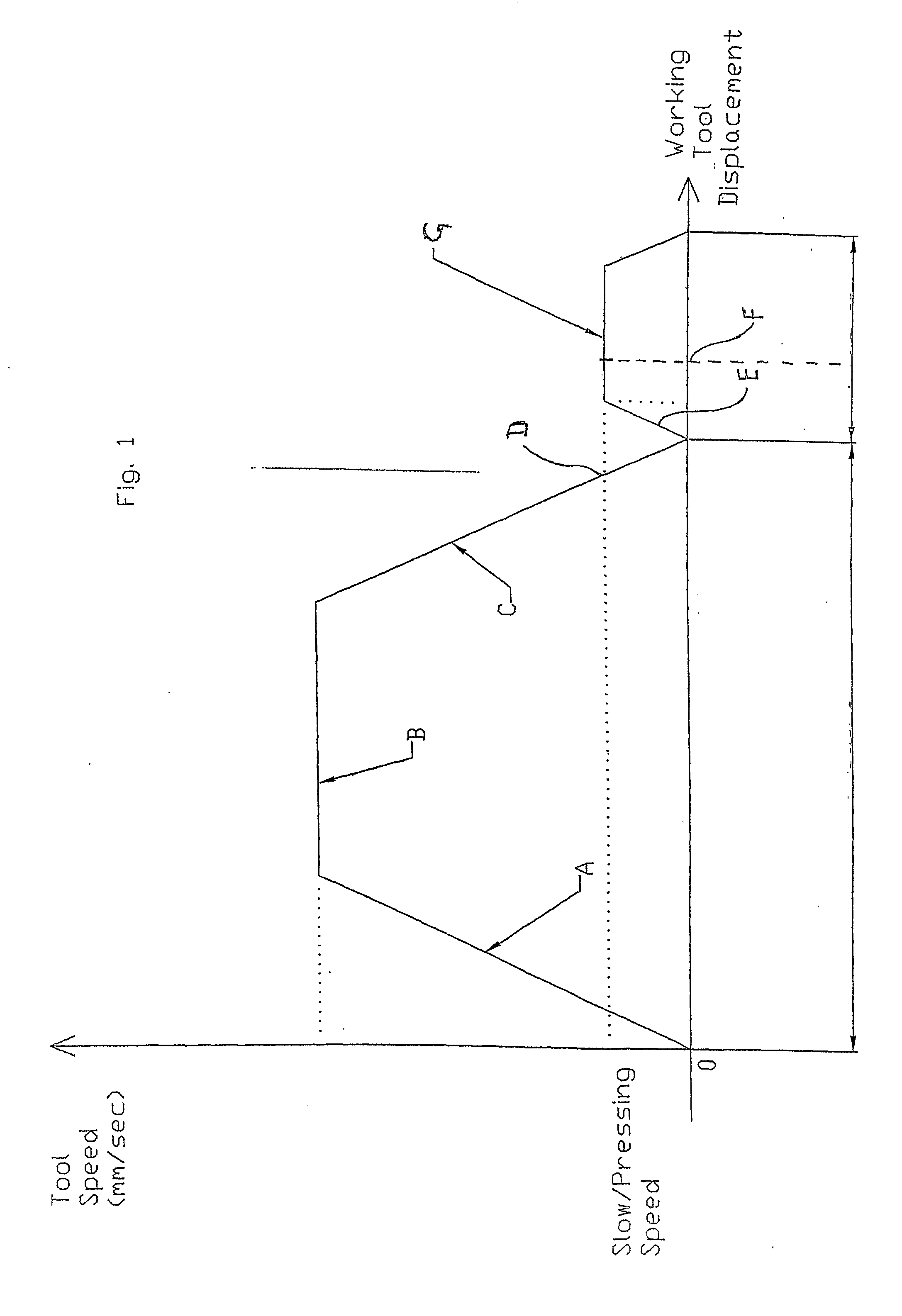
[0074]Referring initially to FIG. 1, this depicts a graph of velocity (y-axis in millimetre per second) of a tool of an industrial machine against displacement (x-axis) of the tool. In particular, the graph depicted relates to the working tool of a press brake. Section A of the graph shows acceleration of the tool. In this example, a downward stroke of the press is envisaged, though the same principle applies to upstroking machines. It will be appreciated that the present invention may also be applicable to other industrial machines, such as lathes and milling machines. Nominal high speed of the tool is reached (e.g., at approximately 150 mms−1), and thereafter plateaus out to a steady velocity shown as Section B. Section C of the graph shows deceleration of the tool to a pressing or crawl speed (e.g., to 10 mms−1). In FIG. 1, the tool actually comes to a halt (velocity=zero) where the deceleration line (Section C) meets the displacement x-axis of the graph. In the example discussed...


PUM


Abstract

An imaging system (40), safety system (58) or combined imaging and safety system (FIG. 1) for an industrial machine (20), including a light transmitter (26) and a corresponding receiver (28). In an imaging application, image data relating to a machine tool (22) and/or work piece (32) is derived from said at least one receiver and processed by an image processing means to determine information regarding said tool and/or tool position and/or extent of work carried out on said work piece. A screen (34, 46), such as a shadow screen, can be used to form an image of a profile of the tool tip and end of the workpiece. Took tip position and extent of work on the workpiece can be derived from the image, e.g., via a camera viewing an image formed on the screen. Multiple cameras may be used. A safety system application (FIGS. 10a to 10d) for halting the machine or tool when a light beam is interrupted can include a broad or block beam (62) and can provide progressive muting of beam interruption detection by progressively muting detection. Progressive muting can be achieved by systematically disregarding or muting signals from rows of receiver array elements as the beam passes through a mute point (66) ahead of the tool tip (60).

Description

FIELD OF THE INVENTION[0001]The present invention is generally directed to alight beam system and method for applicable to an industrial machine. In particular, the present invention relates to a light beam safety system and also to a system for automatically determining the status of material being worked by the industrial machine, such as industrial presses, press brakes or guillotines, and also industrial lathes, such as CNC lathes. Although the present invention will now be described with respect to press brakes for ease of understanding, it is to be appreciated that other applications of the present invention, such as on milling and turning machines, CNC machines and presses in general, are also envisaged to fall within the scope and ambit of the present invention.BACKGROUND OF THE INVENTION[0002]The Applicant has previously developed safety systems for industrial presses utilizing one or more light sources, each emitting a single continuous planar laser beam having a generally...

Claims


Application Information

Patent Timeline
Patent Type & Authority Applications(United States)
IPC IPC(8): H04N7/18H01L31/16
CPCB21D55/00B30B15/28F16P3/144F16P3/142F16P3/14
Inventor APPLEYARD, ROBERT MEREDITHSTANEV, DIMITRE STANTCHEVGOULD, PAUL
Owner LAZER SAFE PTY LTD
Why Eureka
Try Eureka