Dc/dc converter and ac/dc converter

a technology of ac/dc converter and converter, which is applied in the direction of electric variable regulation, process and machine control, instruments, etc., can solve the problems of reducing reducing the power ripple and/or feedback of the supply side, and comparatively high power ripple on the load (e.g. battery), etc., so as to reduce the number of capacitors, the effect of reducing the power ripple and/or feedback

Active Publication Date: 2010-09-02
BRUSA HYPOWER AG
View PDF25 Cites 42 Cited by
  • Summary
  • Abstract
  • Description
  • Claims
  • Application Information

AI Technical Summary

Benefits of technology

[0022]It is advantageous if one capacitor each is connected in parallel to one inverter each and/or one capacitor each is connected in parallel to one rectifier each. In this way, power ripples and/or feedbacks to the supply side can be particularly readily reduced since the already comparatively smooth DC voltage is further smoothed.
[0023]It is furthermore advantageous if a common capacitor is connected in parallel to the inverters and/or a common capacitor is connected in parallel to the rectifiers. This variant of the invention, too, ensures a particularly good reduction of power ripples and/or feedbacks to the supply side, but the number of capacitors is reduced in this variant. The circuit is therefore technically simpler as a whole.
[0024]It is advantageous if one rectifying element is connected antiparallel to one switching element each of an inverter and one switching element is connected antiparallel to one rectifying element each of a rectifier. The DC/DC converter can then convert electrical energy not only in one direction but also in the opposite direction and in principle therefore permits bidirectional operation. Suitable switching elements are, for example, components from power electronics, in particular transistors or thyristors. The abovementioned converters, i.e. passive rectifiers, active rectifiers or active inverters, can therefore also be used in any desired combination, i.e. for example a passive rectifier combined with an active inverter.
[0025]It is also advantageous if the control signal is a square-wave signal. This signal can easily be generated and is therefore p...

Problems solved by technology

The power of the DC/DC converters and/or AC/DC converters, which in some cases is considerable, unfortunately often leads in the case of a conventional design to compa...

Method used


Image

  • Dc/dc converter and ac/dc converter
  • Dc/dc converter and ac/dc converter
  • Dc/dc converter and ac/dc converter

Examples


Embodiment Construction

[0038]In the figures of the drawing, identical and similar parts are provided with identical reference numerals, and elements and features having a similar function are provided—unless stated otherwise—with identical reference numerals but different indices.

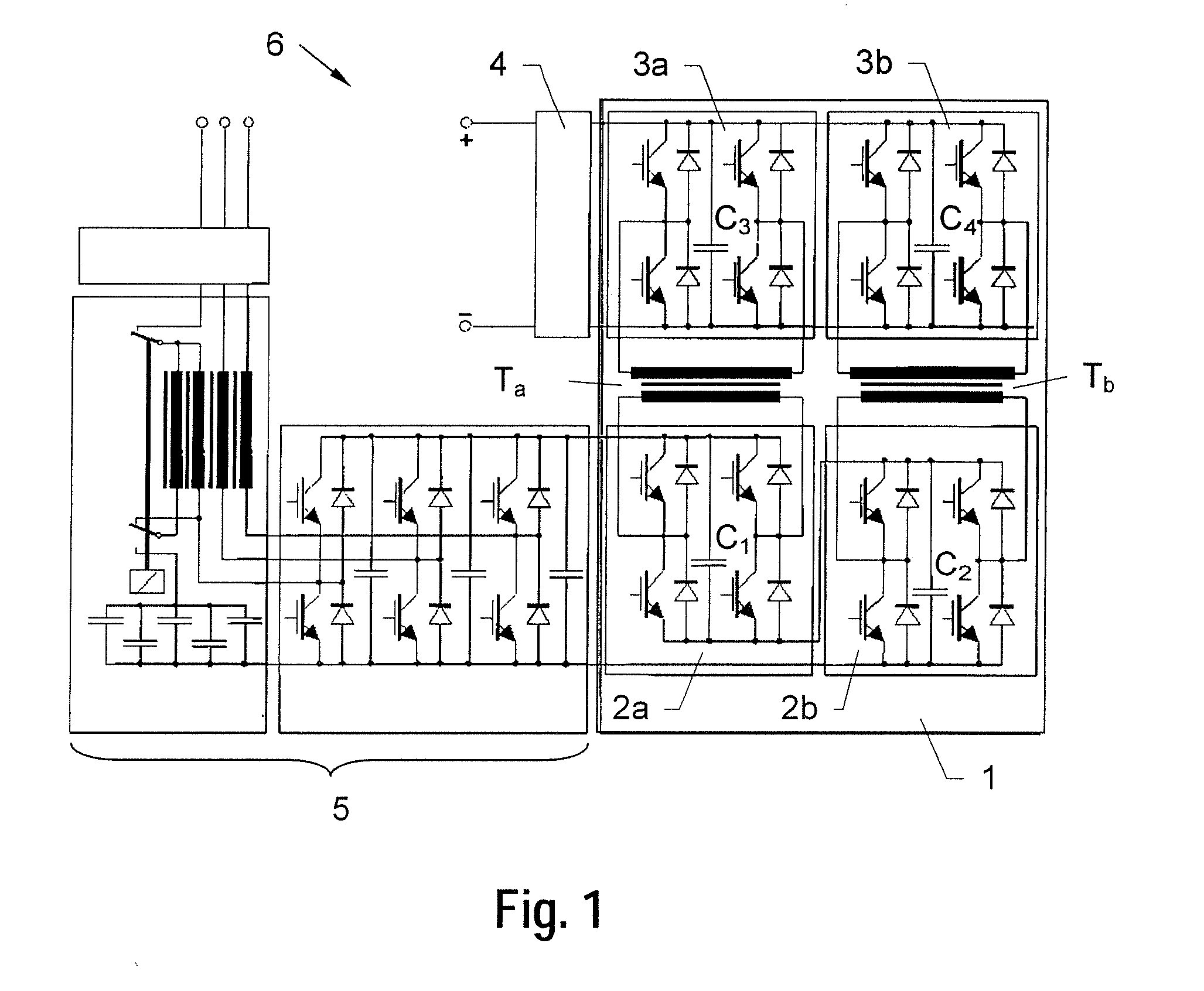
[0039]FIG. 1 shows a DC / DC converter 1 having two two-pole inverters 2a, 2b connected in series, with one capacitor C1, C2 each connected parallel thereto. The inverters 2a, 2b in turn are connected to one primary side each of two transformers Ta, Tb (in this case with separate cores). One secondary side each of the transformers Ta, Tb is connected to one two-pole rectifier 3a, 3b each and to one capacitor C3, C4 each connected parallel thereto. The rectifiers 3a, 3b in turn are connected in parallel and are provided via a filter 4 for connection of a load. The capacitors C1 . . . C4 shown in FIG. 1 are advantageous but by no means essential. Furthermore, instead of the capacitors C3 and C4, one capacitor can be provided for both...


PUM


Abstract

A DC/DC converter (1) having a plurality n of two-pole inverters (2a, 2b) connected in parallel or in series, n transformers (Ta, Tb) and n two-pole rectifiers (3a, 3b) connected in parallel or in series is described. One inverter (2a, 2b) each and one rectifier (3a, 3b) each are connected to a transformer (Ta, Tb). The inverters (2a, 2b, 2a′, 2b′) are in turn connected to a control which is provided for frequency-synchronous actuation of the inverters (2a, 2b, 2a′, 2b′) with a 180°/n phase shift. According to the invention, leakage inductances (LS1, LS2) of the transformers (Ta, Tb, Ta′, Tb′), together with capacitors (C1, C2) of the inverters (2a, 2b , 2a′, 2b′) and/or capacitors (C3, C4) of the rectifiers (3a, 3b, 3a′, 3b′), form in each case a resonating circuit whose resonant frequency is substantially twice as great as a clock frequency of the control signal. Furthermore, an AC/DC converter (6) is described which has a DC/DC converter (1) according to the invention with an AC/DC stage (5) connected on the input side.

Description

[0001]This application claims benefit of priority to prior U.S. provisional application No. 61 / 228,141 filed on Jul. 23, 2009, as a non-provisional thereof; the present application also claims benefit as a continuation of PCT International Application No. PCT / IB2010 / 050401 filed on Jan. 29, 2010; parent PCT International Application No. PCT / IB2010 / 050401 claims benefit of priority to Swiss national applications no. CH-01059 / 09 filed on Jul. 8, 2009, and CH-00136 / 09 filed on Jan. 29, 2009; parent PCT International Application No. PCT / IB2010 / 050401 also claims benefit of priority to prior U.S. provisional application No. 61 / 148,377 filed on Jan. 29 2009, as a non-provisional thereof; all of these prior applications, U.S. 61 / 228,141, PCT / IB2010 / 050401, Swiss 01059 / 09, Swiss 00136 / 09, and U.S. 61 / 148,377 are all incorporated herein by reference in their respective entireties, for all intents and purposes, each as if fully set forth identically herein.BACKGROUND OF THE INVENTION[0002]The...

Claims


Application Information

Patent Timeline
IPC IPC(8): H02M3/335
CPCH02M3/33584H02M5/4585H02M7/066H02M1/10Y02B70/1433Y02B70/1441Y02B70/145H02M7/219Y02B70/10H02M3/335H02M5/458H02M7/06
Inventor KRAUSE, AXEL
Owner BRUSA HYPOWER AG
Why Eureka
Try Eureka